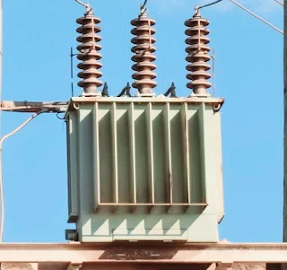
Showing posts with label Transformer. Show all posts

Friday, July 26, 2024

Resonant transformer how to work

 Understanding Resonant Transformers: How They Work


Resonant transformers, often referred to as Tesla coils, are specialized electrical transformers that operate based on the principle of resonance. These devices are capable of generating high-voltage, high-frequency alternating current (AC) electricity. Resonant transformers have various applications, from wireless power transmission to radio frequency applications and even impressive electrical displays.


Basic Principle of Resonance


The fundamental principle behind resonant transformers is resonance, a phenomenon that occurs when an inductor and a capacitor are tuned to oscillate at the same frequency. In a resonant transformer, the primary and secondary coils are designed to have matching resonant frequencies. When an AC is applied to the primary coil, it creates a magnetic field that induces a voltage in the secondary coil. Due to resonance, the energy transfer between the coils is maximized, resulting in high voltage output.

Resonant transformers


 Components of a Resonant Transformer


1.Primary Coil:

 This is the coil connected to the power source. It consists of a few turns of thick wire and is responsible for creating the initial magnetic field.


2. Secondary Coil:

The secondary coil has many more turns than the primary coil. It is where the high voltage is generated. The high number of turns allows it to step up the voltage significantly.


3. Capacitors:

Both the primary and secondary circuits include capacitors. These capacitors are crucial for achieving resonance. In the primary circuit, the capacitor stores energy and releases it in pulses, creating oscillations. In the secondary circuit, the capacitor helps tune the circuit to the correct resonant frequency.


4. Spark Gap:

 This is a device used to periodically interrupt the current in the primary circuit, creating pulses of high voltage. The spark gap helps in creating the oscillating current necessary for resonance.


Working Mechanism


When an AC power source is applied to the primary coil, it charges the primary capacitor. Once the capacitor is fully charged, it discharges through the primary coil, creating a magnetic field. This magnetic field induces a voltage in the secondary coil. Due to the resonant frequency matching between the primary and secondary coils, the energy transfer is very efficient, resulting in a high-voltage AC output in the secondary coil.


The spark gap plays a critical role by interrupting the current flow in the primary circuit, allowing the capacitor to recharge and discharge repeatedly. This periodic charging and discharging create a series of high-frequency oscillations, which are transferred to the secondary coil.


Applications


1. Wireless Power Transmission:

 One of the most promising applications of resonant transformers is in wireless power transfer. By using resonant inductive coupling, power can be transmitted over short distances without the need for physical connectors.


2. Medical Devices:

 Resonant transformers are used in medical devices such as MRI machines, where high-frequency magnetic fields are essential.


3. Radio Frequency Applications:

 They are also used in radio transmitters and receivers, where they help in tuning circuits to specific frequencies.


4. Educational and Entertainment Displays:

 Resonant transformers, particularly Tesla coils, are popular in educational demonstrations and entertainment due to their ability to produce impressive electrical arcs and sparks.


In conclusion, resonant transformers are fascinating devices that leverage the principles of resonance to achieve efficient energy transfer and generate high voltages. Their unique characteristics make them valuable in various applications, from wireless power to medical technology and beyond.

Toroidal Transformer

 Toroidal Transformer: Working Principle and Applications


A toroidal transformer is a type of transformer with a donut-shaped core made from ferromagnetic materials like iron or ferrite. This design offers several advantages over traditional laminated core transformers, including improved efficiency, reduced electromagnetic interference, and compact size. Let's delve into the working principle and various applications of toroidal transformers.

Toroidal transformers 


 Working Principle


The working principle of a toroidal transformer is fundamentally the same as any other transformer, relying on Faraday's Law of Electromagnetic Induction. However, its unique toroidal (circular) shape and construction provide distinct operational benefits.


1. Core Construction: 

The toroidal core is wound from a continuous strip of ferromagnetic material, forming a closed loop without gaps. This design minimizes core losses and increases efficiency.


2.Primary Winding: 

When an alternating current (AC) is applied to the primary winding, it generates a magnetic field that circulates uniformly around the toroidal core. The winding is evenly distributed along the core, reducing leakage inductance and electromagnetic interference.


3.Magnetic Flux: 

The generated magnetic flux remains confined within the core due to its closed-loop shape. This efficient flux confinement reduces stray magnetic fields and minimizes electromagnetic interference with surrounding electronic components.


4. Secondary Winding: 

The secondary winding is also distributed uniformly along the core. The changing magnetic flux in the core induces an electromotive force (EMF) in the secondary winding, based on Faraday’s Law.


5. Voltage Transformation:

 The voltage transformation ratio between the primary and secondary windings is determined by their turns ratio. Like other transformers, a toroidal transformer can step up or step down voltage levels based on the winding ratio.


6. Efficiency and Losses:

 Toroidal transformers are highly efficient due to reduced core losses (hysteresis and eddy current losses) and minimized leakage inductance. The uniform winding distribution further enhances their performance by reducing resistive losses in the windings.


Applications of Toroidal Transformers


Toroidal transformers are used in various applications, thanks to their efficiency, compact size, and low electromagnetic interference. Here are some common applications:


1. Audio Equipment:

 Toroidal transformers are favored in audio amplifiers and other high-fidelity audio equipment due to their low electromagnetic interference, which helps maintain audio signal integrity.


2.Medical Devices:

 The low electromagnetic interference and compact size of toroidal transformers make them suitable for sensitive medical equipment, where space is limited and signal interference must be minimized.


3.Telecommunications:

 Toroidal transformers are used in telecommunications equipment to ensure reliable signal transmission and reception, owing to their efficient operation and reduced noise.


4. Power Supplies:

 They are commonly used in switch-mode power supplies (SMPS) and uninterruptible power supplies (UPS) for their efficiency and ability to handle high-frequency operations.


5. Industrial Control Systems:

 Toroidal transformers are used in industrial control systems and automation equipment, providing reliable and efficient power conversion in compact form factors.


6. Renewable Energy Systems:

 In renewable energy applications, such as solar inverters and wind turbine controllers, toroidal transformers are employed for efficient energy conversion and minimal electromagnetic interference.


7. Lighting Systems:

 They are used in lighting systems, including LED drivers and halogen lamp transformers, for efficient power conversion and compact design.


8.Instrumentation: 

Toroidal transformers are used in precision instrumentation and measurement devices due to their high efficiency and low noise characteristics.


 Advantages of Toroidal Transformers


-High Efficiency:

 Reduced core and winding losses result in higher efficiency compared to conventional transformers.

Compact Size: 

The toroidal design allows for a more compact and lightweight transformer, saving space in various applications.

Low Electromagnetic Interference (EMI): 

The closed-loop core design minimizes stray magnetic fields, reducing interference with nearby electronic components.

Reduced Audible Noise:

 The uniform winding and efficient core design result in quieter operation, which is beneficial in audio and medical applications.


Better Thermal Performance:

 The compact and efficient design leads to better heat dissipation, enhancing the transformer's thermal performance.


In conclusion, toroidal transformers offer significant advantages in terms of efficiency, size, and reduced electromagnetic interference, making them ideal for a wide range of applications, from audio equipment to renewable energy systems. Their unique construction and operational principles allow for improved performance and reliability in various electrical and electronic devices.

Rectifier transformer how to work

Rectifier transformer how to work:

A rectifier transformer is a type of electrical transformer used to convert alternating current (AC) to direct current (DC). It combines the functions of a transformer and a rectifier. Here's below how to work rectifier transformer working principle:


AC Input:

 The rectifier transformer receives AC voltage from the power source.


Voltage Transformation:

 The transformer portion of the rectifier transformer steps up or steps down the voltage to the required level. This is done through electromagnetic induction using primary and secondary windings.


Rectification: 

The transformed AC voltage is then fed into the rectifier part of the system. The rectifier consists of diodes or other rectifying components that convert AC to DC by allowing current to flow in only one direction.


Filtering:

After rectification, the DC output may still have some AC components (ripple). Filters, usually made of capacitors and inductors, smooth out these ripples to produce a steady DC output.


Output:

 The final DC output is delivered to the load, which could be various types of equipment or devices that require DC power to operate.

Rectifier transformer 


Rectifier transformers are commonly used in industrial applications such as electrolysis, traction, HVDC transmission, and large DC motor drives. They are designed to handle high power levels and provide reliable DC output from an AC source.

Wednesday, July 24, 2024

Working Principle of Isolation Transformers

  Working Principle of Isolation Transformers


1. Primary and Secondary Windings:


Primary Winding: 

Connected to the input power source.

Secondary Winding:

 Connection the output load.

The windings are electrically isolated from each other.


 2. Electromagnetic Induction:

An AC voltage applied to the primary winding generates a magnetic field in the transformer's core.

- This magnetic field induces a voltage in the secondary winding due to electromagnetic induction.


3. Electrical Isolation:

- The lack of direct electrical connection between the primary and secondary windings ensures that any electrical faults or surges on the input side do not directly affect the output side, providing protection and safety.


4. Voltage Transformation:

- Isolation transformers can be designed to maintain the same voltage level (1:1 ratio) or to step up or step down the voltage, although the primary purpose is isolation.


5. Noise Reduction:

- They can filter out electrical noise and interference from the input power, providing cleaner power to sensitive equipment.


Applications of Isolation Transformers


1. Safety:

- Used in medical equipment to protect patients and staff from electrical shock.

- Employed in industrial settings to protect workers from electrical hazards.

Isolation transformer


2. Noise Reduction:

- Used in audio and video equipment to prevent hums and interference.

- Installed in sensitive electronic devices to ensure clean power supply and reduce electromagnetic interference (EMI).


 3. Power Quality:

- Used in laboratories and research facilities to provide a stable and noise-free power supply.

- Implemented in data centers and IT equipment to ensure reliable operation.


4. Ground Loop Elimination:

- Used in communication systems to prevent ground loops and associated noise problems.

- Applied in instrumentation and measurement equipment to maintain accuracy and integrity of signals.


5. Isolation in Testing:

- Used in testing and repair of electrical and electronic equipment to isolate the device under test from the power source.

- Essential in calibration labs to ensure precise and safe measurements.

6. Renewable Energy Systems:


- Used in solar power and wind power systems to isolate and protect the inverter and other sensitive components from the grid.


Isolation transformers are crucial for ensuring safety, improving power quality, and reducing noise in a wide range of applications across various industries.

Tuesday, July 23, 2024

A furnace transformer

 A furnace transformer working principle:


A furnace transformer is a critical component in heating systems, especially those that utilize forced air furnaces. It plays a pivotal role in ensuring that the electrical components of the furnace receive the appropriate voltage for operation. Here’s an in-depth look at how a furnace transformer works and its importance in a heating system.


What is a Furnace Transformer?


A furnace transformer is an electrical device that converts high voltage electricity from your home's main power supply to a lower voltage suitable for the furnace's control circuits. Typically, a furnace transformer converts 120V or 240V AC from the main power supply to 24V AC, which is the standard operating voltage for most furnace control systems.

Furnace Transformer 


How Does a Furnace Transformer Work?


1.Step-Down Voltage Conversion:

The primary function of a furnace transformer is to step down the voltage. The transformer has two sets of coils: the primary winding and the secondary winding. The primary winding is connected to the high voltage input (usually 120V or 240V), while the secondary winding provides the lower voltage output (commonly 24V).


When high voltage electricity flows through the primary winding, it creates a magnetic field around the transformer. This magnetic field induces a lower voltage in the secondary winding due to the principle of electromagnetic induction. The reduced voltage in the secondary winding is then used to power the furnace’s control circuits.


2. Ensuring Safe Operation:


By stepping down the voltage, the furnace transformer ensures that the electrical components of the furnace operate safely and efficiently. Higher voltages can be dangerous and could damage sensitive control circuits, leading to potential malfunctions or safety hazards.


3.Powering Control Circuits:


The 24V output from the transformer powers various control circuits within the furnace, including the thermostat, gas valve, and ignition system. These components rely on the lower voltage to operate correctly. The thermostat, for instance, uses the 24V supply to control the furnace’s operation, signaling when to turn the heating on or off based on the room temperature.


Importance of a Properly Functioning Furnace Transformer


1. Reliability and Efficiency:


A properly functioning furnace transformer ensures the reliability and efficiency of the heating system. If the transformer fails, the furnace control circuits will not receive the necessary power, leading to system shutdowns or erratic operation. Regular maintenance and inspection of the transformer can help prevent unexpected failures and maintain the efficiency of the furnace.


2. Safety:


Safety is a crucial aspect of any heating system. A malfunctioning transformer can cause over-voltage or under-voltage conditions, potentially damaging the furnace’s control circuits or creating a fire hazard. Ensuring that the transformer is in good working condition is vital for the overall safety of the heating system.


3. Compatibility:


Using the correct transformer for your furnace model is essential. Different furnaces may require transformers with specific voltage ratings and power capacities. Installing an incompatible transformer can lead to improper operation or damage to the furnace.


Troubleshooting Furnace Transformer Issues:


1. Testing Voltage Output:


One of the common methods to check the functionality of a furnace transformer is to test its voltage output using a multimeter. By measuring the voltage across the secondary winding, you can determine if the transformer is providing the correct 24V output. If the voltage is significantly lower or higher, the transformer may be faulty and require replacement.


2. Inspecting for Physical Damage:


Inspecting the transformer for any signs of physical damage, such as burn marks or melted components, can also indicate issues. Any visible damage usually means the transformer needs to be replaced.


 3. Listening for Humming Noises:


A loud humming noise from the transformer can be a sign of internal problems. While a slight hum is normal due to the magnetic field, excessive noise may indicate a malfunction.


Conclusion:

A furnace transformer is a small but crucial component in a heating system, ensuring that the furnace’s control circuits receive the appropriate voltage for safe and efficient operation. Regular maintenance and proper troubleshooting can help keep the transformer and, consequently, the furnace, in good working condition. Understanding its function and importance can aid homeowners in maintaining their heating systems effectively.

Distribution Transformers

  How Distribution Transformers Work: An In-Depth Look

Distribution transformers are essential components in the electrical power distribution system. They play a crucial role in stepping down high voltage electricity from transmission lines to lower voltages suitable for use in homes, businesses, and industries. This article delves into the workings of distribution transformers, their types, components, and their significance in the electrical grid.

Distribution Transformer


The Basics of Distribution Transformers

A distribution transformer is an electrical device that transfers electrical energy between two or more circuits through electromagnetic induction. It consists of primary and secondary windings wound around a magnetic core. A primary coil is connected to the high voltage supply, and the secondary winding is connected to the low voltage distribution lines. The transformer operates on the principle of mutual induction, where an alternating current (AC) in the primary winding creates a varying magnetic field that induces a voltage in the secondary winding.


 Working Principle

The working principle of a distribution transformer is based on Faraday's Law of Electromagnetic Induction. When an AC voltage is applied to the primary winding, it creates a time-varying magnetic flux in the core. This changing flux induces a voltage in the secondary winding proportional to the turns ratio of the transformer. For example, if the primary winding has 1000 turns and the secondary winding has 100 turns, the turns ratio is 10:1, and the voltage in the secondary winding will be one-tenth of the primary voltage.


 Components of a Distribution Transformer

A distribution transformer comprises several key components:

1. Core:

 The core is typically made of laminated silicon steel to reduce energy losses due to eddy currents. The core provides a less reluctance path for the magnetic flux.

2. Windings:

 The windings are made of copper or aluminum and are insulated to prevent short circuits. The primary winding is connected to the high voltage supply, and the secondary winding is connected to the load.

3. Insulation: 

Insulating materials, such as oil or solid insulation, are used to insulate the windings and the core to prevent electrical breakdown.

4. Tank:

 The transformer tank houses the core and windings and is filled with insulating oil that provides cooling and insulation.

5. Bushings:

 Bushings are insulating structures that allow electrical connections to pass through the transformer tank without causing a short circuit.

6. Cooling System:

 Distribution transformers are equipped with cooling systems, such as radiators or fans, to dissipate the heat generated during operation.


 Types of Distribution Transformers

Distribution transformers can be classified based on their construction, phase, and insulation:

1. Pole-mounted Transformers:

 These transformers are mounted on utility poles and are commonly used in rural and suburban areas. They are typically single-phase or three-phase units.

2. Pad-mounted Transformers:

 These transformers are installed on concrete pads and are used in urban areas where underground distribution systems are prevalent. They are enclosed in tamper-proof housings for safety.

3. Dry-type Transformers:

 These transformers use air as the insulating medium instead of oil. They are used in indoor applications where fire safety is a concern.

Significance in the Electrical Grid

Distribution transformers are crucial for the efficient operation of the electrical grid. They ensure that electricity is delivered at the appropriate voltage levels to end-users, minimizing energy losses during transmission. By stepping down high voltages to safer levels, distribution transformers enhance the safety and reliability of the power supply. Moreover, they help in maintaining voltage stability and reducing power outages, contributing to the overall efficiency and reliability of the electrical distribution system.


Conclusion

 Their ability to step down high voltages to usable levels makes them essential for delivering electricity to homes, businesses, and industries. Understanding their working principle, components, and types helps in appreciating their role in ensuring a reliable and efficient power supply. As the demand for electricity continues to grow, the importance of distribution transformers in maintaining a stable and efficient electrical grid cannot be overstated.

Monday, July 22, 2024

current transformer (CT)

current transformer (CT)


The current transformer (CT) is  type of transformer used to mak measure alternating current (AC). To  produces a reduced current accurately proportional to the current in the circuit, which can be conveniently connected to measuring and recording instruments. 


Current transformer 

A current transformer (CT) is a type of transformer used to measure alternating current (AC). It produces a reduced current accurately proportional to the current in the circuit, which can be conveniently connected to measuring and recording instruments. Here’s how a current transformer works:

Current transformer 


Basic Principle


1.Primary Winding: 

The primary winding of a current transformer is connected in series with the line carrying the current to be measured. This winding usually consists of one or very few turns of thick wire.


2. Secondary Winding: 

The secondary winding consists of many turns of finer wire. This winding is connected to a measuring device, such as an ammeter or the input of a protective relay.


3. Magnetic Core:

 The primary and secondary windings are wound on a magnetic core, which provides a low reluctance path for the magnetic flux.


Working Mechanism


1.Current Flow: 

When current flows through the primary winding, it generates a magnetic field around the conductor.


2. Magnetic Induction:

 The magnetic field induces a current in the secondary winding proportional to the current in the primary winding. The ratio of the primary to secondary currents is the inverse of the turns ratio of the transformer.


3. Load Connection:

 The secondary winding is connected to a load, usually an ammeter or other measuring instrument. The induced current in the secondary winding is scaled down from the primary current by the ratio of the number of turns in the primary and secondary windings.


Key Points

Current Ratio:

 The current ratio (primary to secondary current) is determined by the turns ratio of the transformer. For example, if the primary winding has 1 turn and the secondary has 100 turns, the current ratio is 100:1.


Safety:

 CTs are used for safely measuring high currents. The secondary current is much lower and safer to handle, making it easier to connect to measuring instruments.


Accuracy:

 CTs are designed to provide accurate current measurements over a wide range of currents. They are crucial for protection systems in electrical power distribution.


Burden

The load connected to the secondary winding is referred to as the burden. The CT must be designed to work accurately with the expected burden, which includes the impedance of the connected instruments and wiring.


 Applications


Metering: 

Used in power meters to measure electrical consumption in residential, commercial, and industrial settings.


-Protection:

 Used in protective relays in substations to detect fault conditions and initiate circuit breaker operations.


Monitoring:

 Used in various monitoring devices to provide data on current flow for analysis and system management.


Example


Imagine a CT with a primary winding of 1 turn and a secondary winding of 100 turns. If 1000 A flows through the primary winding, the secondary winding will carry 10 A, assuming a perfect transformer with no losses. The ammeter connected to the secondary winding will thus measure 10 A, representing 1000 A in the primary circuit.


Understanding CTs is crucial for engineers and technicians involved in electrical power systems, ensuring accurate measurement and safe handling of high currents.

Different between circuit breakers and isolator

 Circuit breakers and isolators are both electrical devices used in power systems, but they have different functions and are used for distin...