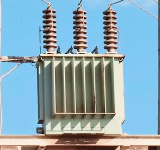
Showing posts with label Transformer. Show all posts

Friday, July 26, 2024

Resonant transformer how to work

 Understanding Resonant Transformers: How They Work


Resonant transformers, often referred to as Tesla coils, are specialized electrical transformers that operate based on the principle of resonance. These devices are capable of generating high-voltage, high-frequency alternating current (AC) electricity. Resonant transformers have various applications, from wireless power transmission to radio frequency applications and even impressive electrical displays.


Basic Principle of Resonance


The fundamental principle behind resonant transformers is resonance, a phenomenon that occurs when an inductor and a capacitor are tuned to oscillate at the same frequency. In a resonant transformer, the primary and secondary coils are designed to have matching resonant frequencies. When an AC is applied to the primary coil, it creates a magnetic field that induces a voltage in the secondary coil. Due to resonance, the energy transfer between the coils is maximized, resulting in high voltage output.

Resonant transformers


 Components of a Resonant Transformer


1.Primary Coil:

 This is the coil connected to the power source. It consists of a few turns of thick wire and is responsible for creating the initial magnetic field.


2. Secondary Coil:

The secondary coil has many more turns than the primary coil. It is where the high voltage is generated. The high number of turns allows it to step up the voltage significantly.


3. Capacitors:

Both the primary and secondary circuits include capacitors. These capacitors are crucial for achieving resonance. In the primary circuit, the capacitor stores energy and releases it in pulses, creating oscillations. In the secondary circuit, the capacitor helps tune the circuit to the correct resonant frequency.


4. Spark Gap:

 This is a device used to periodically interrupt the current in the primary circuit, creating pulses of high voltage. The spark gap helps in creating the oscillating current necessary for resonance.


Working Mechanism


When an AC power source is applied to the primary coil, it charges the primary capacitor. Once the capacitor is fully charged, it discharges through the primary coil, creating a magnetic field. This magnetic field induces a voltage in the secondary coil. Due to the resonant frequency matching between the primary and secondary coils, the energy transfer is very efficient, resulting in a high-voltage AC output in the secondary coil.


The spark gap plays a critical role by interrupting the current flow in the primary circuit, allowing the capacitor to recharge and discharge repeatedly. This periodic charging and discharging create a series of high-frequency oscillations, which are transferred to the secondary coil.


Applications


1. Wireless Power Transmission:

 One of the most promising applications of resonant transformers is in wireless power transfer. By using resonant inductive coupling, power can be transmitted over short distances without the need for physical connectors.


2. Medical Devices:

 Resonant transformers are used in medical devices such as MRI machines, where high-frequency magnetic fields are essential.


3. Radio Frequency Applications:

 They are also used in radio transmitters and receivers, where they help in tuning circuits to specific frequencies.


4. Educational and Entertainment Displays:

 Resonant transformers, particularly Tesla coils, are popular in educational demonstrations and entertainment due to their ability to produce impressive electrical arcs and sparks.


In conclusion, resonant transformers are fascinating devices that leverage the principles of resonance to achieve efficient energy transfer and generate high voltages. Their unique characteristics make them valuable in various applications, from wireless power to medical technology and beyond.

Toroidal Transformer

 Toroidal Transformer: Working Principle and Applications


A toroidal transformer is a type of transformer with a donut-shaped core made from ferromagnetic materials like iron or ferrite. This design offers several advantages over traditional laminated core transformers, including improved efficiency, reduced electromagnetic interference, and compact size. Let's delve into the working principle and various applications of toroidal transformers.

Toroidal transformers 


 Working Principle


The working principle of a toroidal transformer is fundamentally the same as any other transformer, relying on Faraday's Law of Electromagnetic Induction. However, its unique toroidal (circular) shape and construction provide distinct operational benefits.


1. Core Construction: 

The toroidal core is wound from a continuous strip of ferromagnetic material, forming a closed loop without gaps. This design minimizes core losses and increases efficiency.


2.Primary Winding: 

When an alternating current (AC) is applied to the primary winding, it generates a magnetic field that circulates uniformly around the toroidal core. The winding is evenly distributed along the core, reducing leakage inductance and electromagnetic interference.


3.Magnetic Flux: 

The generated magnetic flux remains confined within the core due to its closed-loop shape. This efficient flux confinement reduces stray magnetic fields and minimizes electromagnetic interference with surrounding electronic components.


4. Secondary Winding: 

The secondary winding is also distributed uniformly along the core. The changing magnetic flux in the core induces an electromotive force (EMF) in the secondary winding, based on Faraday’s Law.


5. Voltage Transformation:

 The voltage transformation ratio between the primary and secondary windings is determined by their turns ratio. Like other transformers, a toroidal transformer can step up or step down voltage levels based on the winding ratio.


6. Efficiency and Losses:

 Toroidal transformers are highly efficient due to reduced core losses (hysteresis and eddy current losses) and minimized leakage inductance. The uniform winding distribution further enhances their performance by reducing resistive losses in the windings.


Applications of Toroidal Transformers


Toroidal transformers are used in various applications, thanks to their efficiency, compact size, and low electromagnetic interference. Here are some common applications:


1. Audio Equipment:

 Toroidal transformers are favored in audio amplifiers and other high-fidelity audio equipment due to their low electromagnetic interference, which helps maintain audio signal integrity.


2.Medical Devices:

 The low electromagnetic interference and compact size of toroidal transformers make them suitable for sensitive medical equipment, where space is limited and signal interference must be minimized.


3.Telecommunications:

 Toroidal transformers are used in telecommunications equipment to ensure reliable signal transmission and reception, owing to their efficient operation and reduced noise.


4. Power Supplies:

 They are commonly used in switch-mode power supplies (SMPS) and uninterruptible power supplies (UPS) for their efficiency and ability to handle high-frequency operations.


5. Industrial Control Systems:

 Toroidal transformers are used in industrial control systems and automation equipment, providing reliable and efficient power conversion in compact form factors.


6. Renewable Energy Systems:

 In renewable energy applications, such as solar inverters and wind turbine controllers, toroidal transformers are employed for efficient energy conversion and minimal electromagnetic interference.


7. Lighting Systems:

 They are used in lighting systems, including LED drivers and halogen lamp transformers, for efficient power conversion and compact design.


8.Instrumentation: 

Toroidal transformers are used in precision instrumentation and measurement devices due to their high efficiency and low noise characteristics.


 Advantages of Toroidal Transformers


-High Efficiency:

 Reduced core and winding losses result in higher efficiency compared to conventional transformers.

Compact Size: 

The toroidal design allows for a more compact and lightweight transformer, saving space in various applications.

Low Electromagnetic Interference (EMI): 

The closed-loop core design minimizes stray magnetic fields, reducing interference with nearby electronic components.

Reduced Audible Noise:

 The uniform winding and efficient core design result in quieter operation, which is beneficial in audio and medical applications.


Better Thermal Performance:

 The compact and efficient design leads to better heat dissipation, enhancing the transformer's thermal performance.


In conclusion, toroidal transformers offer significant advantages in terms of efficiency, size, and reduced electromagnetic interference, making them ideal for a wide range of applications, from audio equipment to renewable energy systems. Their unique construction and operational principles allow for improved performance and reliability in various electrical and electronic devices.

Rectifier transformer how to work

Rectifier transformer how to work:

A rectifier transformer is a type of electrical transformer used to convert alternating current (AC) to direct current (DC). It combines the functions of a transformer and a rectifier. Here's below how to work rectifier transformer working principle:


AC Input:

 The rectifier transformer receives AC voltage from the power source.


Voltage Transformation:

 The transformer portion of the rectifier transformer steps up or steps down the voltage to the required level. This is done through electromagnetic induction using primary and secondary windings.


Rectification: 

The transformed AC voltage is then fed into the rectifier part of the system. The rectifier consists of diodes or other rectifying components that convert AC to DC by allowing current to flow in only one direction.


Filtering:

After rectification, the DC output may still have some AC components (ripple). Filters, usually made of capacitors and inductors, smooth out these ripples to produce a steady DC output.


Output:

 The final DC output is delivered to the load, which could be various types of equipment or devices that require DC power to operate.

Rectifier transformer 


Rectifier transformers are commonly used in industrial applications such as electrolysis, traction, HVDC transmission, and large DC motor drives. They are designed to handle high power levels and provide reliable DC output from an AC source.

Wednesday, July 24, 2024

Working Principle of Isolation Transformers

  Working Principle of Isolation Transformers


1. Primary and Secondary Windings:


Primary Winding: 

Connected to the input power source.

Secondary Winding:

 Connection the output load.

The windings are electrically isolated from each other.


 2. Electromagnetic Induction:

An AC voltage applied to the primary winding generates a magnetic field in the transformer's core.

- This magnetic field induces a voltage in the secondary winding due to electromagnetic induction.


3. Electrical Isolation:

- The lack of direct electrical connection between the primary and secondary windings ensures that any electrical faults or surges on the input side do not directly affect the output side, providing protection and safety.


4. Voltage Transformation:

- Isolation transformers can be designed to maintain the same voltage level (1:1 ratio) or to step up or step down the voltage, although the primary purpose is isolation.


5. Noise Reduction:

- They can filter out electrical noise and interference from the input power, providing cleaner power to sensitive equipment.


Applications of Isolation Transformers


1. Safety:

- Used in medical equipment to protect patients and staff from electrical shock.

- Employed in industrial settings to protect workers from electrical hazards.

Isolation transformer


2. Noise Reduction:

- Used in audio and video equipment to prevent hums and interference.

- Installed in sensitive electronic devices to ensure clean power supply and reduce electromagnetic interference (EMI).


 3. Power Quality:

- Used in laboratories and research facilities to provide a stable and noise-free power supply.

- Implemented in data centers and IT equipment to ensure reliable operation.


4. Ground Loop Elimination:

- Used in communication systems to prevent ground loops and associated noise problems.

- Applied in instrumentation and measurement equipment to maintain accuracy and integrity of signals.


5. Isolation in Testing:

- Used in testing and repair of electrical and electronic equipment to isolate the device under test from the power source.

- Essential in calibration labs to ensure precise and safe measurements.

6. Renewable Energy Systems:


- Used in solar power and wind power systems to isolate and protect the inverter and other sensitive components from the grid.


Isolation transformers are crucial for ensuring safety, improving power quality, and reducing noise in a wide range of applications across various industries.

Tuesday, July 23, 2024

A furnace transformer

 A furnace transformer working principle:


A furnace transformer is a critical component in heating systems, especially those that utilize forced air furnaces. It plays a pivotal role in ensuring that the electrical components of the furnace receive the appropriate voltage for operation. Here’s an in-depth look at how a furnace transformer works and its importance in a heating system.


What is a Furnace Transformer?


A furnace transformer is an electrical device that converts high voltage electricity from your home's main power supply to a lower voltage suitable for the furnace's control circuits. Typically, a furnace transformer converts 120V or 240V AC from the main power supply to 24V AC, which is the standard operating voltage for most furnace control systems.

Furnace Transformer 


How Does a Furnace Transformer Work?


1.Step-Down Voltage Conversion:

The primary function of a furnace transformer is to step down the voltage. The transformer has two sets of coils: the primary winding and the secondary winding. The primary winding is connected to the high voltage input (usually 120V or 240V), while the secondary winding provides the lower voltage output (commonly 24V).


When high voltage electricity flows through the primary winding, it creates a magnetic field around the transformer. This magnetic field induces a lower voltage in the secondary winding due to the principle of electromagnetic induction. The reduced voltage in the secondary winding is then used to power the furnace’s control circuits.


2. Ensuring Safe Operation:


By stepping down the voltage, the furnace transformer ensures that the electrical components of the furnace operate safely and efficiently. Higher voltages can be dangerous and could damage sensitive control circuits, leading to potential malfunctions or safety hazards.


3.Powering Control Circuits:


The 24V output from the transformer powers various control circuits within the furnace, including the thermostat, gas valve, and ignition system. These components rely on the lower voltage to operate correctly. The thermostat, for instance, uses the 24V supply to control the furnace’s operation, signaling when to turn the heating on or off based on the room temperature.


Importance of a Properly Functioning Furnace Transformer


1. Reliability and Efficiency:


A properly functioning furnace transformer ensures the reliability and efficiency of the heating system. If the transformer fails, the furnace control circuits will not receive the necessary power, leading to system shutdowns or erratic operation. Regular maintenance and inspection of the transformer can help prevent unexpected failures and maintain the efficiency of the furnace.


2. Safety:


Safety is a crucial aspect of any heating system. A malfunctioning transformer can cause over-voltage or under-voltage conditions, potentially damaging the furnace’s control circuits or creating a fire hazard. Ensuring that the transformer is in good working condition is vital for the overall safety of the heating system.


3. Compatibility:


Using the correct transformer for your furnace model is essential. Different furnaces may require transformers with specific voltage ratings and power capacities. Installing an incompatible transformer can lead to improper operation or damage to the furnace.


Troubleshooting Furnace Transformer Issues:


1. Testing Voltage Output:


One of the common methods to check the functionality of a furnace transformer is to test its voltage output using a multimeter. By measuring the voltage across the secondary winding, you can determine if the transformer is providing the correct 24V output. If the voltage is significantly lower or higher, the transformer may be faulty and require replacement.


2. Inspecting for Physical Damage:


Inspecting the transformer for any signs of physical damage, such as burn marks or melted components, can also indicate issues. Any visible damage usually means the transformer needs to be replaced.


 3. Listening for Humming Noises:


A loud humming noise from the transformer can be a sign of internal problems. While a slight hum is normal due to the magnetic field, excessive noise may indicate a malfunction.


Conclusion:

A furnace transformer is a small but crucial component in a heating system, ensuring that the furnace’s control circuits receive the appropriate voltage for safe and efficient operation. Regular maintenance and proper troubleshooting can help keep the transformer and, consequently, the furnace, in good working condition. Understanding its function and importance can aid homeowners in maintaining their heating systems effectively.

Distribution Transformers

  How Distribution Transformers Work: An In-Depth Look

Distribution transformers are essential components in the electrical power distribution system. They play a crucial role in stepping down high voltage electricity from transmission lines to lower voltages suitable for use in homes, businesses, and industries. This article delves into the workings of distribution transformers, their types, components, and their significance in the electrical grid.

Distribution Transformer


The Basics of Distribution Transformers

A distribution transformer is an electrical device that transfers electrical energy between two or more circuits through electromagnetic induction. It consists of primary and secondary windings wound around a magnetic core. A primary coil is connected to the high voltage supply, and the secondary winding is connected to the low voltage distribution lines. The transformer operates on the principle of mutual induction, where an alternating current (AC) in the primary winding creates a varying magnetic field that induces a voltage in the secondary winding.


 Working Principle

The working principle of a distribution transformer is based on Faraday's Law of Electromagnetic Induction. When an AC voltage is applied to the primary winding, it creates a time-varying magnetic flux in the core. This changing flux induces a voltage in the secondary winding proportional to the turns ratio of the transformer. For example, if the primary winding has 1000 turns and the secondary winding has 100 turns, the turns ratio is 10:1, and the voltage in the secondary winding will be one-tenth of the primary voltage.


 Components of a Distribution Transformer

A distribution transformer comprises several key components:

1. Core:

 The core is typically made of laminated silicon steel to reduce energy losses due to eddy currents. The core provides a less reluctance path for the magnetic flux.

2. Windings:

 The windings are made of copper or aluminum and are insulated to prevent short circuits. The primary winding is connected to the high voltage supply, and the secondary winding is connected to the load.

3. Insulation: 

Insulating materials, such as oil or solid insulation, are used to insulate the windings and the core to prevent electrical breakdown.

4. Tank:

 The transformer tank houses the core and windings and is filled with insulating oil that provides cooling and insulation.

5. Bushings:

 Bushings are insulating structures that allow electrical connections to pass through the transformer tank without causing a short circuit.

6. Cooling System:

 Distribution transformers are equipped with cooling systems, such as radiators or fans, to dissipate the heat generated during operation.


 Types of Distribution Transformers

Distribution transformers can be classified based on their construction, phase, and insulation:

1. Pole-mounted Transformers:

 These transformers are mounted on utility poles and are commonly used in rural and suburban areas. They are typically single-phase or three-phase units.

2. Pad-mounted Transformers:

 These transformers are installed on concrete pads and are used in urban areas where underground distribution systems are prevalent. They are enclosed in tamper-proof housings for safety.

3. Dry-type Transformers:

 These transformers use air as the insulating medium instead of oil. They are used in indoor applications where fire safety is a concern.

Significance in the Electrical Grid

Distribution transformers are crucial for the efficient operation of the electrical grid. They ensure that electricity is delivered at the appropriate voltage levels to end-users, minimizing energy losses during transmission. By stepping down high voltages to safer levels, distribution transformers enhance the safety and reliability of the power supply. Moreover, they help in maintaining voltage stability and reducing power outages, contributing to the overall efficiency and reliability of the electrical distribution system.


Conclusion

 Their ability to step down high voltages to usable levels makes them essential for delivering electricity to homes, businesses, and industries. Understanding their working principle, components, and types helps in appreciating their role in ensuring a reliable and efficient power supply. As the demand for electricity continues to grow, the importance of distribution transformers in maintaining a stable and efficient electrical grid cannot be overstated.

Monday, July 22, 2024

current transformer (CT)

current transformer (CT)


The current transformer (CT) is  type of transformer used to mak measure alternating current (AC). To  produces a reduced current accurately proportional to the current in the circuit, which can be conveniently connected to measuring and recording instruments. 


Current transformer 

A current transformer (CT) is a type of transformer used to measure alternating current (AC). It produces a reduced current accurately proportional to the current in the circuit, which can be conveniently connected to measuring and recording instruments. Here’s how a current transformer works:

Current transformer 


Basic Principle


1.Primary Winding: 

The primary winding of a current transformer is connected in series with the line carrying the current to be measured. This winding usually consists of one or very few turns of thick wire.


2. Secondary Winding: 

The secondary winding consists of many turns of finer wire. This winding is connected to a measuring device, such as an ammeter or the input of a protective relay.


3. Magnetic Core:

 The primary and secondary windings are wound on a magnetic core, which provides a low reluctance path for the magnetic flux.


Working Mechanism


1.Current Flow: 

When current flows through the primary winding, it generates a magnetic field around the conductor.


2. Magnetic Induction:

 The magnetic field induces a current in the secondary winding proportional to the current in the primary winding. The ratio of the primary to secondary currents is the inverse of the turns ratio of the transformer.


3. Load Connection:

 The secondary winding is connected to a load, usually an ammeter or other measuring instrument. The induced current in the secondary winding is scaled down from the primary current by the ratio of the number of turns in the primary and secondary windings.


Key Points

Current Ratio:

 The current ratio (primary to secondary current) is determined by the turns ratio of the transformer. For example, if the primary winding has 1 turn and the secondary has 100 turns, the current ratio is 100:1.


Safety:

 CTs are used for safely measuring high currents. The secondary current is much lower and safer to handle, making it easier to connect to measuring instruments.


Accuracy:

 CTs are designed to provide accurate current measurements over a wide range of currents. They are crucial for protection systems in electrical power distribution.


Burden

The load connected to the secondary winding is referred to as the burden. The CT must be designed to work accurately with the expected burden, which includes the impedance of the connected instruments and wiring.


 Applications


Metering: 

Used in power meters to measure electrical consumption in residential, commercial, and industrial settings.


-Protection:

 Used in protective relays in substations to detect fault conditions and initiate circuit breaker operations.


Monitoring:

 Used in various monitoring devices to provide data on current flow for analysis and system management.


Example


Imagine a CT with a primary winding of 1 turn and a secondary winding of 100 turns. If 1000 A flows through the primary winding, the secondary winding will carry 10 A, assuming a perfect transformer with no losses. The ammeter connected to the secondary winding will thus measure 10 A, representing 1000 A in the primary circuit.


Understanding CTs is crucial for engineers and technicians involved in electrical power systems, ensuring accurate measurement and safe handling of high currents.

Working Principle of an Autotransformer

 Understanding the Working Principle of an Autotransformer


An autotransformer is an electrical transformer with only one winding, unlike conventional transformers that have separate primary and secondary windings. This unique design allows the autotransformer to be more compact, cost-effective, and efficient. Here's a detailed look into its working principle and applications.

Auto transformer 


Basic Structure and Components


An autotransformer consists of a single winding that is tapped at certain points to create electrical connections for both the primary and secondary circuits. The winding is divided into two parts: the common portion (shared by both primary and secondary) and the series portion (unique to each). The common portion is the segment of the winding that is used for both the input and output, while the series portion is used to adjust the voltage.


Voltage Transformation


The voltage transformation in an autotransformer is achieved through the principle of electromagnetic induction, similar to conventional transformers. The transformation ratio is determined by the number of turns in the winding between the taps:


\[ \frac{V_1}{V_2} = \frac{N_1}{N_2} \]


Where \( V_1 \) and \( V_2 \) are the voltages across the primary and secondary windings, and \( N_1 \) and \( N_2 \) are the number of turns in the primary and secondary windings, respectively. By varying the position of the tap, the voltage ratio can be adjusted, allowing the autotransformer to step up or step down the voltage as required.


Working Principle


1.Single Winding Operation:

 The single winding of the autotransformer serves both as the input (primary) and the output (secondary). This is different from a conventional transformer that has separate windings for each.


2. Tap Adjustments:

Taps are made at various points along the winding to obtain the desired voltage levels. For example, if the tap is at the midpoint of the winding, the output voltage will be half of the input voltage, effectively stepping down the voltage by a factor of two.


3. Current Flow:

The current flows through the winding such that the primary and secondary currents are combined in the common portion, which reduces the amount of copper needed and increases the efficiency.


 Advantages of Autotransformers


1. Cost-Effective:


 Autotransformers use less copper and core material compared to conventional transformers, making them cheaper to manufacture.


2. High Efficiency:

 Due to the single winding design, autotransformers have lower losses and higher efficiency, especially in applications where the voltage change is relatively small.


3. Compact Size:

 The single winding reduces the size and weight of the transformer, making it more compact and easier to install in limited spaces.


4. Versatility:

 They are highly versatile and can be used in various applications such as voltage regulation, load sharing, and power distribution.


Applications


Autotransformers are widely used in numerous applications, including:


1. Power Transmission and Distribution:

 In electrical power systems, autotransformers are used for voltage regulation and stabilization, improving the efficiency of power transmission and distribution networks.


2. Industrial Applications:

 They are employed in industrial equipment where precise voltage control is necessary, such as in motor drives and industrial machinery.


3. Laboratory and Testing Equipment:

 Autotransformers are used in laboratories for testing purposes, where variable voltage supply is required.


4. Railway Electrification:

In railway systems, autotransformers help in maintaining the desired voltage levels for efficient train operation.


Conclusion


The autotransformer is a unique and efficient device that offers significant advantages over conventional transformers, particularly in terms of cost, size, and efficiency. By understanding its working principle and applications, one can appreciate the critical role it plays in modern electrical systems. Whether in power distribution, industrial settings, or specialized equipment, the autotransformer remains a vital component in managing and transforming electrical energy effectively.

Sunday, July 21, 2024

Audio transformer

 An Audio Transformer is a type of model specifically designed for tasks involving audio data, such as speech recognition, audio classification, and audio generation. Here’s a high-level overview of how an audio transformer works:


Audio transformer how to work:

1.Input Representation:

 Audio data, typically a waveform, is first transformed into a suitable format. This often involves converting the waveform into a spectrogram using techniques like Short-Time Fourier Transform (STFT) or Mel-Frequency Cepstral Coefficients (MFCCs). 


2.Embedding Layer: 

The spectrogram is then converted into a sequence of feature vectors. This step is analogous to the tokenization and embedding steps in NLP, where words are converted into dense vectors. Each time slice of the spectrogram can be treated as a token and mapped to a higher-dimensional space.

Audio transformer 


3.Positional Encoding:

 Transformers are inherently unaware of the order of the input tokens. Positional encodings are added to the input embeddings to provide the model with information about the position of each token in the sequence. This helps the model to understand the temporal nature of the audio data.


4.Transformer Layers: 

The core of the transformer model consists of multiple layers of self-attention and feedforward networks. The self-attention mechanism allows the model to weigh the importance of different parts of the input sequence when making predictions. Each transformer layer comprises:

 Multi-Head Self-Attention:

 This mechanism enables the model to focus on different parts of the sequence simultaneously and learn various aspects of the data.

   Feedforward Neural Networks:

 These layers apply non-linear transformations to the output of the attention mechanism, allowing the model to learn complex patterns.


5.Output Layer: 

After passing through several transformer layers, the final layer(s) produce the output. Depending on the task, this might be:

   Classification:

 For tasks like audio classification, a softmax layer may be used to output class probabilities.

  Regression:

 For tasks requiring continuous output, like speech synthesis, a suitable regression output layer is used.

  Sequence Generation:

 For tasks like speech recognition, a sequence of tokens (such as characters or words) is generated.


6.Training:

 The model is trained end-to-end using a suitable loss function. For classification tasks, cross-entropy loss is common, while for sequence generation, a combination of cross-entropy and other sequence-based losses may be used.


Audio transformers can leverage pre-training on large datasets and fine-tuning for specific tasks, similar to NLP transformers like BERT and GPT. They can achieve state-of-the-art performance on many audio-related tasks due to their ability to capture long-range dependencies and complex patterns in the data.

Saturday, July 20, 2024

Power Transformers:

 Power Transformers: Backbone of Electrical Power Distribution


The Power transformers are indispensable components of electrical power systems, playing a crucial role in the transmission and distribution of electrical energy. They are pivotal in ensuring the efficient and safe delivery of electricity from power plants to end users. This article delves into the workings, types, applications, and advancements in power transformers.

Power Transformers:


 Understanding Power Transformers


The power transformer is  . It functions on the principle of Faraday's law of electromagnetic induction, which states that a change in the magnetic field within a closed loop induces an electromotive force (EMF) in the wire forming the loop. Power transformers primarily step up (increase) or step down (decrease) voltage levels to facilitate the efficient transmission of electricity over long distances and its safe distribution to homes and businesses.


Types of Power Transformers


Power transformers are classified based on various criteria such as their function, construction, and cooling methods. The main types include:


1. tep-Up Transformers:

These transformers increase the voltage from a lower level to a higher level. They are typically used at power generation stations to elevate the voltage for efficient transmission over long distances, minimizing energy loss.


2. Step-Down Transformers:

 These transformers decrease the voltage from a higher level to a lower level. They are commonly used in distribution networks to reduce the voltage to safer levels for residential and commercial use.


3. Three-Phase Transformers:

 These are widely used in electrical power systems as most power generation and distribution is done in three-phase. They are more efficient and economical for high-power applications compared to single-phase transformers.


4. Autotransformers:

 Unlike traditional transformers, autotransformers share common windings for both primary and secondary circuits. They are more efficient and cost-effective for applications requiring small voltage changes.


5. Isolation Transformers:

 These transformers provide electrical isolation between primary and secondary windings. They are used for safety purposes and to eliminate ground loops in sensitive equipment.


6. Oil-Cooled Transformers:

 These transformers use oil as a cooling medium. The oil circulates through the transformer, dissipating heat generated during operation. They are robust and suitable for high-capacity applications.


7. Dry-Type Transformers:

 These transformers use air as the cooling medium instead of oil. They are safer for indoor applications and environments where oil-based cooling poses fire hazards.


Applications of Power Transformers


Power transformers are integral to the functioning of power systems. Their applications include:


1. Power Generation:

 At power plants, step-up transformers increase the voltage generated by the turbines to transmission levels.


2. Transmission:

 High-voltage transformers enable the efficient transmission of electricity over vast distances, reducing energy losses.


3. Distribution:

Step-down transformers at substations reduce the voltage to distribution levels suitable for industrial, commercial, and residential use.


4. Industrial Applications:

 Transformers are used in various industrial processes requiring different voltage levels for equipment operation.


5. Renewable Energy Integration:

Transformers play a key role in integrating renewable energy sources such as solar and wind into the grid by matching the generated voltage with the grid voltage.


Advancements and Innovations


The field of power transformers has seen significant advancements aimed at improving efficiency, reliability, and sustainability:


1. Smart Transformers:

 Equipped with sensors and communication technologies, smart transformers provide real-time monitoring and diagnostics, enhancing the reliability and efficiency of power systems.


2. Eco-Friendly Transformers:

 Innovations in materials and design have led to the development of eco-friendly transformers using biodegradable oils and materials with lower environmental impact.


3. Compact and Lightweight Designs:

 Advances in materials and engineering have resulted in more compact and lightweight transformers without compromising performance, making them suitable for space-constrained installations.


4. Enhanced Cooling Techniques:

 Improved cooling technologies, including forced air and liquid cooling systems, have increased the capacity and lifespan of transformers.


Conclusion


Power transformers are the backbone of modern electrical power systems, ensuring the efficient transmission and distribution of electricity. As the demand for electricity grows and renewable energy sources become more prevalent, the role of power transformers will continue to evolve. Ongoing advancements in technology and design will further enhance their efficiency, reliability, and environmental sustainability, securing their place as a critical component in the global energy infrastructure.

Friday, July 19, 2024

Different between power transformer and disturbing transformers

 Different between power transformer and disturbing transformers


Power transformers and distribution transformers serve different purposes within an electrical power system:


1. Power Transformers:


   Function:

 Primarily used in transmission networks to step up (increase) or step down (decrease) voltage levels. They are crucial for efficient long-distance high-voltage transmission.

 Location: 

Typically found in power generation stations and high-voltage transmission substations.

  Capacity: 

Designed to handle high power levels, often in the range of hundreds of MVA (Mega Volt-Amperes).

  Operation:

 Usually operates at nearly full load for maximum efficiency.

  Size and Cost: 

Larger and more expensive compared to distribution transformers.

 Cooling System:

 Generally have more complex cooling systems due to higher power handling.


2.Distribution Transformers:

  Function:

 Used to step down the voltage to levels suitable for consumer use. They are essential for delivering electricity from the transmission system to individual homes and businesses.

   Location:

 Typically found on utility poles, ground-level pads, or within buildings in residential and commercial areas.

   Capacity: 

Designed for lower power levels, usually ranging from a few kVA (Kilovolt-Amperes) to several MVA.

  Operation:

 Often operate at varying loads, depending on the demand from end users.

Size and Cost:

 Smaller and less expensive than power transformers.

  Cooling System: 

Generally have simpler cooling systems, suitable for lower power handling.


In summary, power transformers are used for high-voltage, high-power transmission over long distances, while distribution transformers are used to provide usable voltage levels to end users.

Way at is transformer rated kva, not in kw

Way at is transformer rated kva, not in kw


 Transformers are rated in kilovolt-amperes (kVA) rather than kilowatts (kW) due to the nature of their operation and the types of loads they serve. This distinction is essential for accurately representing the capacity and performance of transformers in electrical systems. Here's why kVA is the preferred unit of measurement:


Understanding kVA and kW


To comprehend the reasoning behind this, it's important to understand the difference between kVA and kW. Kilovolt-amperes (kVA) measure apparent power, which combines both real power (measured in kW) and reactive power (measured in kilovars, or kVAR). Real power is the actual power consumed by the electrical equipment to perform work, such as lighting, heating, or running motors. Reactive power, on the other hand, does not perform useful work but is necessary to maintain the voltage levels required for equipment to function correctly. The relationship between these three types of power is expressed in the formula:


\[ \text{Apparent Power (S)} = \sqrt{\text{Real Power (P)}^2 + \text{Reactive Power (Q)}^2} \]


Nature of Transformer Loads


Transformers supply power to various types of electrical loads, including resistive loads (like heaters), inductive loads (like motors and transformers), and capacitive loads (like capacitor banks). These loads draw both real and reactive power. Since transformers must handle the total power (apparent power) drawn by these loads, their rating needs to reflect this comprehensive demand, which is why kVA is used. This ensures that transformers are appropriately sized to handle both the real and reactive components of the power they will deliver.


Power Factor Considerations


The power factor (PF) of a load is the ratio of real power to apparent power, and it varies based on the type of load. For purely resistive loads, the power factor is 1 (or 100%), meaning all the apparent power is converted into real power. However, most practical loads have a power factor less than 1 due to the presence of reactive components. By rating transformers in kVA, manufacturers avoid assumptions about the power factor of the loads, ensuring the rating remains applicable regardless of the load's power factor.


 Universality and Standardization


Using kVA for transformer ratings provides a universal and standardized way to specify their capacity. It simplifies the design, selection, and comparison of transformers without needing to account for varying power factors. This uniform approach is particularly beneficial for manufacturers, designers, and engineers when specifying and integrating transformers into diverse electrical systems.


 Safety and Efficiency


Transformers are designed to operate efficiently within their rated capacity. Rating transformers in kVA helps ensure they are not overloaded, which can lead to overheating, reduced lifespan, and potential failure. It allows for better management of the thermal and electrical stresses on the transformer, maintaining safety and reliability in power distribution.


Conclusion


In summary, transformers are rated in kVA rather than kW to accurately represent their ability to handle the total power demanded by various electrical loads. This rating accounts for both real and reactive power, ensuring the transformer is appropriately sized and capable of operating safely and efficiently. By using kVA, manufacturers provide a standardized and universally applicable measure of transformer capacity, facilitating effective design, selection, and operation in diverse electrical systems.

Friday, July 5, 2024

How work Transformer

Transformers are used to increase (step up) or decrease (step down) voltage levels in power systems. Here's a basic overview of how transformers work:

1. Primary Coil: 

The transformer has a primary coil (or winding) connected to the input voltage source.

2. Magnetic Core: 

The primary coil is wrpped around a magnetic core, which provides a path for the magnetic flux. The core is usually made of laminated silicon steel to reduce energy losses.

3. Electromagnetic Induction.


 When an alternating current (AC) flows through the primary coil, it creates a changing magnetic field in the core. 

4. Secondary Coil. 


The secondary coil is also wrapped around the magnetic core but is electrically isolated from the primary coil. The induced voltage in the secondary coil depends on the number of turns in the coil relative to the primary coil.


5. Voltage Transformation:


 The voltage transformation ratio between the primary and secondary coils is determined by the ratio of the number of turns in each coil. For example, if the secondary coil has twice as many turns as the primary coil, the voltage in the secondary coil will be twice the input voltage (step-up transformer). Conversely, if the secondary coil has half as many turns as the primary coil, the voltage in the secondary coil will be half the input voltage (step-down transformer).


 Types of Transformers

1. Step-Up Transformer. Increases voltage from primary to secondary coil.

2. Step-Down Transformer:

 Decreases voltage from primary to secondary coil.

3. Isolation Transformer.

 Provides electrical isolation without changing voltage levels.


4. Autotransformer: 

Uses a single coil that acts as both primary and secondary, sharing part of the windings.


Power Distribution:

 Step-up transformers are used at power plants to increase voltage for transmission over long distances. Step-down transformers are used at substations to reduce voltage for safe distribution to homes and businesses.
Symbol 


Electronics:

Transformers are used in various electronic devices to provide the necessary voltage levels for different components.

-Isolation.

Isolation transformers are used to protect sensitive equipment and provide safety by isolating circuits.

In summary, transformers are essential components in the electrical power industry, enabling the efficient transmission and distribution of electrical energy by adjusting voltage levels to meet the needs of different applications.
Similarity 34%
Three Phase Transformer Design Using Ansys Maxwell
A transformer is an electrical device that transfers electrical energy between two or m

Different between circuit breakers and isolator

 Circuit breakers and isolators are both electrical devices used in power systems, but they have different functions and are used for distin...