Showing posts with label Testing meter. Show all posts

Sunday, July 14, 2024

LUX Meter

 A lux meter is an instrument used to measure illuminance, which is the amount of light that falls on a surface.

 Illuminance is measured in lux (lx), and a lux meter provides readings that help determine the intensity of light in a given area. Lux meters are commonly used in various fields, including photography, cinematography, horticulture, and workplace safety, to ensure proper lighting conditions.

How used:

Using a lux meter involves a few straightforward steps:

1.Turn on the Lux Meter: 

Power on the device according to the manufacturer's instructions.

2. Set the Range:

 If your lux meter has multiple range settings, select the appropriate range for your expected light level. Start with a higher range if unsure.

3. Position the Sensor: 

Place the sensor of the lux meter in the location where you want to measure the light intensity. Ensure the sensor is oriented correctly, typically facing the light source or the surface being measured.

4. Take the Reading: 

Allow the lux meter to stabilize and then take the reading displayed on the screen. Some meters may have a hold function to lock the reading.

5.Record the Reading:

 Note the lux value for your records. If multiple measurements are needed, repeat the process in different locations or at different times.

6. Turn Off the Meter:

 After use, turn off the lux meter to conserve battery life.
LUX METER 


Additional Tips:

- Ensure the sensor is free from obstructions and clean for accurate readings.
- Avoid shadows or reflections that could affect the measurement.
- Calibrate the lux meter regularly as recommended by the manufacturer to maintain accuracy.

Friday, July 5, 2024

A clamp meter is a What is a clamp meter used for?

 A clamp meter is a versatile electrical test tool used for measuring various electrical parameters without having to make direct contact with conductors. Here are some of the main uses of a clamp meter:


1.Measuring Current:

 The primary use of a clamp meter is to measure AC and sometimes DC current without interrupting the circuit. The clamp function allows it to measure the magnetic field around a conductor to determine the current flowing through it.


2. Voltage Measurement: 

Many clamp meters also have the capability to measure voltage, both AC and DC, using test leads.


3. Resistance Measurement:

 Clamp meters can measure the resistance of electrical components and circuits, which is useful for troubleshooting and verifying connections.


4. Continuity Testing:

 This function helps to check if a circuit is complete, meaning there is a continuous path for current flow.


5. Frequency Measurement:

 Some advanced clamp meters can measure the frequency of an AC signal, which is useful in various applications like motor speed control.


6.Diode Testing: 

Some models include a diode test function to check the health of diodes within a circuit.


7. Capacitance Measurement:

 Advanced models can also measure the capacitance of capacitors in a circuit.


Electrical Maintenance:

 Used by electricians to diagnose and fix electrical problems in residential, commercial, and industrial settings.

1.HVAC Systems: 

HVAC technicians use clamp meters to maintain and repair heating, ventilation, and air conditioning systems.

2.Automotive:

 Used by automotive technicians for diagnosing electrical issues in vehicles.

3.Renewable Energy:

 Essential for technicians working with solar panels and wind turbines to measure current and voltage output.


Clamp meters are highly valued for their convenience and safety, as they allow measurements to be taken without physically disconnecting or altering the circuit.

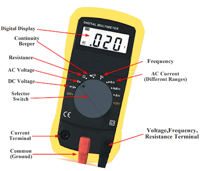
how work multimeter

Components of a Multimeter

1.Shows the measurement readings.
2. Dial/Selector Knob:
Allows you to select the type of measurement (voltage, current, resistance, etc.) and the range.
3. Ports:
 Where the test leads are connected. Common ports are:
 -COM (Common):
 The negative or ground terminal.
 -VΩmA:
 Used for measuring voltage, resistance, and small currents.
 10A: 
Used for measuring higher currents.


4. Test Leads:
 Probes that connect the multimeter to the circuit or component being tested.

 1. Measuring Voltage:
 - DC Voltage (V—), Used for measuring direct current voltage (e.g., batteries, DC power supplies).
 AC Voltage (V~): 
Used for measuring alternating current voltage (e.g., household )
 1. Turn the dial to the appropriate voltage setting (DC or AC).
 2. Plug the black test lead into the COM port and the red test lead into the VΩmA port.
 3. Touch the black probe to the negative side of the circuit and the red probe to the positive side.2. Measuring Current:
 DC Current (A—): Measures direct current.
 AC Current (A~): Measures alternating current.
4.De-energize Circuits.
 Always de-energize circuits before measuring resistance or continuity.
5. Inspect Leads:
 Regularly check test leads for damage and replace them if necessary.

Thursday, July 4, 2024

Megger or Earth testing

1. Safety Precautions:
 - Ensure the equipment is de-energized and disconnected from any live circuits.
 - Wear appropriate personal protective equipment (PPE).
 - Familiarize yourself with the Megger meter's manual and safety instructions.


2. Preparation:

 - Select the appropriate test voltage for your specific application (commonly, Megger meters offer a range of voltages such as 250V, 500V, 1000V, etc.).

 - Connect the test leads to the meter: usually, a Megger meter has three terminals (Line, Earth, and Guard). For basic insulation resistance testing, you typically use the Line and Earth terminals.


3. Connecting to the Equipment:

 - Connect the Line (positive) lead to one conductor of the equipment being tested.

 - Connect the Earth (negative) lead to the ground or another conductor of the equipment.

 - If using the Guard terminal, connect it to a shield or any other part of the equipment that you want to exclude from the measurement.


4. Performing the Test:

 - Turn on the Megger meter and select the appropriate test voltage.

 - Press the test button or switch to apply the voltage to the equipment.

 - Observe the reading on the display. The meter measures the resistance in ohms (often in megaohms).


5. Interpreting Results:

 - A high resistance value typically indicates good insulation.

 - A low resistance value may indicate poor insulation, potential leakage paths, or insulation failure.


6. Completion:

 - After the test, ensure to safely discharge any residual charge in the equipment by shorting the conductors to the ground.

 - Disconnect the test leads and turn off the Megger meter.

 - Record the results for future reference and maintenance purposes.


Always refer to the specific Megger meter’s user manual for detailed instructions and safety guidelines, as procedures can vary slightly depending on the model and application.


Different between circuit breakers and isolator

 Circuit breakers and isolators are both electrical devices used in power systems, but they have different functions and are used for distin...