Showing posts with label Circuit Breaker. Show all posts

Tuesday, November 12, 2024

Different between circuit breakers and isolator

 Circuit breakers and isolators are both electrical devices used in power systems, but they have different functions and are used for distinct purposes:


 1.Functionality:

Circuit Breaker:

 This is an automatic device that interrupts the flow of current in an electrical circuit to protect it from damage due to overloads or short circuits. It can detect faults and trip (open) the circuit automatically.

Isolator:

 This is a manually operated device that isolates a part of the circuit from the main power supply for maintenance or safety purposes. It does not have a mechanism to automatically interrupt the current flow when faults occur.


 2. Operation Under Load:

Circuit Breaker: Can operate under load conditions, meaning it can open and close a circuit that is carrying current.

Isolator: 

Cannot operate under load conditions and must only be operated when the circuit is already de-energized. It is not designed to break a live circuit.


 3.Protective Role:

Circuit Breaker: Provides protection to the system by detecting and interrupting fault conditions, making it a protective device.

-Isolator: Does not provide any protective functions. Its primary role is to ensure safety by isolating a portion of the system for maintenance or emergency purposes.


4.Automation:

-Circuit Breaker: Can be automatic or remotely controlled and often comes equipped with additional protection features such as overload protection, short circuit protection, etc.

Isolator: Is manually operated and does not have any automatic features. It needs to be engaged or disengaged by an operator.


 5. Usage:

Circuit Breaker:

 Used in places where automatic protection is required, such as substations, industrial systems, and residential electrical panels.

Isolator:

 Used primarily as a safety device for disconnecting a part of the electrical system to ensure safe maintenance.


Summary:

In essence, circuit breakers are protective devices that can break the circuit during fault conditions automatically, while isolators are used to ensure safe disconnection for maintenance and can only be operated when the circuit is not carrying current.

Saturday, August 17, 2024

Wi-Fi circuit breaker

 The Future of Home Automation: Wi-Fi Circuit Breakers for App Control


Home automation has revolutionized the way we interact with our living spaces, and Wi-Fi circuit breakers are at the forefront of this innovation. These devices combine the safety features of traditional circuit breakers with the convenience of app-based control, offering homeowners unprecedented control over their electrical systems. 


 What is a Wi-Fi Circuit Breaker?


A Wi-Fi circuit breaker is an advanced electrical switch that can be operated remotely via a smartphone app. Like traditional circuit breakers, they protect your home from electrical overloads and short circuits. However, their Wi-Fi connectivity allows users to monitor and control the electrical circuits in their home from anywhere in the world. 


 Advantages of Wi-Fi Circuit Breakers


The most significant benefit of Wi-Fi circuit breakers is the ability to manage your home’s power usage remotely. Through a user-friendly app, you can turn off specific circuits, schedule power to be cut at certain times, and even monitor energy consumption in real time. This not only enhances safety but also contributes to energy savings, as you can easily identify and reduce unnecessary power usage.


Moreover, Wi-Fi circuit breakers provide real-time alerts in case of electrical faults. This immediate notification system can prevent potential hazards by allowing you to take prompt action, whether you’re at home or away.


Integration with Smart Home Systems


Wi-Fi circuit breakers seamlessly integrate with other smart home systems, such as lighting, security, and HVAC systems. This creates a cohesive and centralized control hub for all your home automation needs. Imagine being able to turn off all the lights and appliances in your home with a single tap on your smartphone        Wi-Fi circuit breakers make this possible.


Conclusion


As smart home technology continues to evolve, Wi-Fi circuit breakers represent a significant leap forward in home automation. They combine safety, convenience, and energy efficiency, making them an essential component of any modern home. With these devices, managing your home’s electrical systems has never been easier or more efficient.

Monday, August 12, 2024

what does Mean (B20) on a circuit breaker?

 The "B20" marking on a circuit breaker indicates two important things:


1. Type of Tripping

 Characteristic (B):

 The letter "B" refers to the type of tripping characteristic of the circuit breaker. In this case, a "B" type breaker is designed to trip when the current exceeds 3 to 5 times the rated current. This type of breaker is generally used for residential or light commercial applications where the connected equipment has low inrush currents, such as lighting and general outlets.


2.Rated Current (20A):

 The number "20" represents the rated current of the circuit breaker, which in this case is 20 amperes (A). This means the breaker is designed to carry a current of up to 20 amps under normal conditions, and it will trip if the current exceeds this rating to protect the circuit from overloads.


In summary, "B20" on the circuit breaker specifies that it is a type B circuit breaker with a 20-ampere current rating.

Or

"B20" on a circuit breaker indicates two things:

1. Type B:

 The "B" denotes the trip curve or the type of the breaker. A Type B breaker trips when the current is between 3 to 5 times the rated current. These breakers are typically used in residential or light commercial applications where the electrical load is more predictable and less prone to surges.

2. 20 Amps:

The "20" refers to the breaker’s rated current capacity in amperes. This means the breaker is designed to handle up to 20 amps of current continuously. If the current exceeds this rating, the breaker will trip to prevent overheating and potential damage to the circuit.

So, a "B20" circuit breaker is a Type B breaker with a 20-ampere rating, typically used in residential or light commercial settings to protect circuits from overloads and short circuits.

Wednesday, August 7, 2024

KM-N2 Gas Detection Device

 KM-N2 Gas Detection Device


The KM-N2 is a specific type of sensor or device often used in industrial or environmental applications for monitoring and measurement. While the exact specifics of the KM-N2 can vary depending on the manufacturer and intended use, a common application is in gas detection or air quality monitoring. Below is a detailed description of the working principle of a generic KM-N2 device, typically used for gas detection.


Working Principle of KM-N2 Gas Detection Device


 Introduction:

The KM-N2 is a sophisticated sensor designed to detect the presence of specific gases in the environment. Its primary use is to ensure safety in industrial settings by monitoring air quality and providing early warnings of hazardous gas levels.


Key Components

1.Sensing Element:

 The core component responsible for detecting gas molecules.

2. Microcontroller: 

Processes the signals from the sensing element and performs necessary calculations.

3. Display/Output Interface:


 Shows the concentration levels of the detected gas.

4.Power Supply: 

Provides the necessary power for the device to operate.

5.Housing:

  Protects the internal components from environmental factors.


Operation Mechanism

1.Gas Diffusion:

 The process begins with the target gas molecules diffusing through the protective housing to reach the sensing element. The design ensures that only the intended gas reaches the sensor while filtering out other impurities.


2. Detection:

 The sensing element typically operates based on a chemical reaction or a physical change when it comes into contact with the target gas. For instance, in an electrochemical sensor, the gas reacts with an electrolyte, causing a change in electrical properties (voltage or current), which is directly proportional to the concentration of the gas.


3.Signal Processing: 

The microcontroller receives the raw signal from the sensing element. It then processes this signal, often using calibration data to convert it into a readable gas concentration value. This step might involve analog-to-digital conversion, signal filtering, and compensation for temperature or humidity effects.


4.Display and Alert: 

The processed data is then displayed on the device’s interface, which could be an LCD screen or LED indicators. If the gas concentration exceeds pre-set safety thresholds, the device triggers alarms (audible and visual) to alert the personnel to take necessary actions.


5.Data Logging and Communication:

 Advanced KM-N2 devices may include features for data logging, storing historical data for trend analysis. Additionally, they can have communication modules (e.g., Wi-Fi, Bluetooth) to transmit data to remote monitoring systems.


pplications

The KM-N2 gas detection devices are crucial in various settings, including:

Industrial Plants:

 Monitoring for leaks of toxic or flammable gases.

Laboratories:

 Ensuring safe levels of gases used in experiments.

Environmental Monitoring:

 Checking air quality in urban areas or near emission sources.

Safety Systems:

 Integrated into larger safety systems to automate responses to detected gas hazards.


Conclusion

The KM-N2 is an essential device for ensuring safety in environments where hazardous gases might be present. Its operation relies on sophisticated sensing technology and robust processing capabilities to provide accurate and reliable gas concentration readings, thereby helping to prevent accidents and health hazards.

Saturday, August 3, 2024

Thermal relay

 The function of thermal relay:


A thermal relay is a protective device used in electrical systems to protect motors and other equipment from overheating due to excessive current. It operates based on the heat generated by the current passing through it. Here’s how it functions:


1. Heating Element:

 The thermal relay has a heating element that heats up when current flows through it. The amount of heat generated is proportional to the current.


2. Bimetallic Strip:

 Attached to the heating element is a bimetallic strip made of two metals with different coefficients of thermal expansion. When heated, the strip bends because one metal expands more than the other.


3. Trigger Mechanism:

 As the bimetallic strip bends, it eventually reaches a point where it triggers a mechanism that opens the relay contacts. This breaks the circuit, stopping the current flow and protecting the equipment.


4. Resetting:

 After the relay trips and cools down, the bimetallic strip returns to its original shape. Some thermal relays reset automatically, while others need to be manually reset.


5. Adjustable Settings:

Many thermal relays have adjustable settings to tailor the trip point to the specific requirements of the system being protected.


Thermal relays are widely used because they are simple, reliable, and provide effective protection against overload conditions.

Friday, August 2, 2024

The Auxiliary Contact Blocks

 The Function of Auxiliary Contact Blocks in Electrical Systems:


Auxiliary contact blocks are critical components in electrical control systems, offering enhanced functionality and flexibility. These devices, often attached to primary control equipment like relays or contactors, extend the control capabilities beyond the basic on-off function. Here, we will delve into the specifics of auxiliary contact blocks, their types, applications, and significance in modern electrical systems.


Understanding Auxiliary Contact Blocks


Auxiliary contact blocks are secondary switching devices used alongside primary control devices. They do not carry the main load current; instead, they provide additional contacts that operate in conjunction with the primary device. These contacts are typically of two types: Normally Open (NO) and Normally Closed (NC). When the primary device is actuated, the auxiliary contacts change their state—NO contacts close and NC contacts open.


Types of Auxiliary Contact Blocks


1. Front-Mounted Auxiliary Contacts: 

These are mounted on the front of the primary device. They are easily accessible and visible, making them convenient for quick modifications or troubleshooting.


2. Side-Mounted Auxiliary Contacts: 

These are attached to the sides of the primary control device. Side mounting allows for more complex configurations and can save space within control panels.


3. Top-Mounted Auxiliary Contacts: 

These are mounted on top of the primary device, often used when additional contacts are required without increasing the footprint of the control device significantly.


4. Plug-In Auxiliary Contacts:

 These offer flexibility and ease of installation, as they can be plugged into the primary device without the need for tools. This feature is particularly useful for modular systems.


 Functions and Applications


Auxiliary contact blocks serve several functions within electrical control systems:


1. MStatus Indication:

 They provide feedback on the status of the primary device. For example, an auxiliary contact block can signal whether a contactor is energized or de-energized, allowing for precise monitoring and control.


2.Interlocking: 

They enable interlocking between different circuits or devices. This is crucial for safety and operational efficiency, preventing conflicting operations. For instance, in motor control circuits, auxiliary contacts can prevent simultaneous forward and reverse commands.


3. Sequential Control:

 They facilitate sequential operations in automated systems. By using auxiliary contacts, a sequence of operations can be set up where the actuation of one device triggers the next step in the sequence. This is common in complex machinery and process control.


4.Alarm and Protection:

 Auxiliary contact blocks can be used to activate alarms or protective devices. If a primary device encounters a fault or abnormal condition, the auxiliary contact can trigger an alarm or shutdown mechanism, enhancing system safety.


5.Load Shedding and Transfer: 


In power management systems, auxiliary contacts help in load shedding and transfer operations. They ensure that critical loads are prioritized during power outages or when switching between different power sources.


Significance in Modern Electrical Systems


The role of auxiliary contact blocks in modern electrical systems cannot be overstated. They enhance the functionality and reliability of control systems in several ways:


Flexibility: 

By adding auxiliary contacts, systems can be easily expanded or modified without the need to replace primary devices. This flexibility is invaluable in dynamic environments where requirements frequently change.


Reliability: 

Auxiliary contacts provide redundant paths for control signals, ensuring that critical operations can continue even if one path fails. This redundancy enhances system reliability and uptime.


Safety:

 Through interlocking and protection functions, auxiliary contact blocks contribute significantly to the safety of electrical systems. They help prevent dangerous conditions and ensure safe operation protocols are followed.


Efficiency: 

In automation and process control, auxiliary contacts streamline operations, making systems more efficient. They enable precise control over complex sequences, reducing downtime and improving productivity.


Conclusion


Auxiliary contact blocks are indispensable in the realm of electrical control systems. Their ability to provide additional control paths, status indication, interlocking, and sequential control makes them vital components in various applications. As electrical systems continue to evolve, the importance of auxiliary contact blocks in enhancing functionality, reliability, and safety will only grow, cementing their role as key enablers of modern automation and control technology.

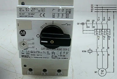
The Function of a Motor Circuit Breaker:

 The Function of a Motor Circuit Breaker


Motor circuit breakers are critical components in electrical systems, specifically designed to protect motors from damage caused by electrical faults. These devices ensure the safe operation of motors by preventing overheating, overcurrent, and short circuits. Understanding the function of motor circuit breakers involves exploring their design, operational principles, and the types of protection they offer.

motor Circuit breaker 


Design and Operational Principles


Motor circuit breakers are similar in appearance and basic function to standard circuit breakers but are tailored to meet the specific needs of motor protection. They typically include both thermal and magnetic protection mechanisms. 


The thermal protection element responds to prolonged overcurrents that may not be large enough to trigger an immediate response but can cause overheating over time. This component uses a bimetallic strip that bends when heated by the passing current. If the current exceeds a safe level for an extended period, the strip will bend sufficiently to trip the breaker and interrupt the circuit.


Magnetic protection, on the other hand, reacts to short-circuit conditions. A solenoid generates a magnetic field proportional to the current flowing through the circuit. If the current spikes abruptly, as in a short circuit, the magnetic field will be strong enough to pull a plunger or trip lever, instantly disconnecting the power to prevent damage to the motor and associated wiring.


 Types of Protection


1. Overload Protection:

 Motors can draw excessive current due to mechanical overloads or electrical faults. The thermal element in the motor circuit breaker detects this overcurrent and trips the circuit if the current remains high for too long. This action protects the motor from overheating and potential damage.


2. Short-Circuit Protection:

 Short circuits can result from faults like insulation failure, wiring errors, or other defects. These faults cause a rapid and significant increase in current, which the magnetic protection element detects and responds to almost instantaneously, disconnecting the power supply to prevent severe damage and possible fire hazards.


3. Phase Failure Protection: 

In three-phase systems, a phase failure or imbalance can severely damage a motor. Some motor circuit breakers are equipped with phase failure protection, which ensures that if one phase drops out or there is a significant imbalance, the breaker will trip to protect the motor.


4. Under-voltage Protection:

 Motors can be damaged if they operate at voltages significantly lower than their rated voltage. Some advanced motor circuit breakers can detect under-voltage conditions and disconnect the motor to prevent damage due to insufficient voltage supply.


 Importance in Motor Protection


Using a motor circuit breaker is essential for the longevity and reliability of motors. Motors are expensive components in industrial and commercial applications, and their failure can result in significant downtime and repair costs. By providing comprehensive protection against various electrical faults, motor circuit breakers help ensure motors operate within safe parameters, enhancing their lifespan and performance.


Furthermore, motor circuit breakers contribute to overall electrical safety. By preventing electrical faults from escalating into dangerous situations, such as electrical fires or severe equipment damage, they play a crucial role in maintaining a safe working environment.


Conclusion:

Motor circuit breakers are indispensable in protecting motors from electrical faults. Their design, which incorporates both thermal and magnetic protection mechanisms, allows them to respond effectively to overcurrents, short circuits, and other anomalies. By offering overload, short-circuit, phase failure, and under-voltage protection, these devices help ensure the safe and efficient operation of motors. Their role in preventing damage and enhancing safety underscores their importance in modern electrical systems, making them a vital component in any setup involving motor-driven equipment.

Wednesday, July 31, 2024

Soft Starter Working Principle

Understanding How a Soft Starter Works:


In industrial applications, electric motors are integral components, driving machinery and processes. However, the direct starting of these motors can cause mechanical stress and electrical issues due to the high inrush current. A soft starter offers a solution to mitigate these problems by gradually ramping up the motor's power supply. This article delves into the workings of a soft starter and its benefits.

Softe starter 


What is a Soft Starter?

The soft starter  an a electronic device used to control a acceleration of an electric motor by gradually increasing the voltage supply. Unlike direct-on-line (DOL) starters, which apply full voltage immediately, soft starters ensure a smooth start, reducing mechanical stress and electrical peaks.


How Does a Soft Starter Work?


1.Initial Voltage Control:


   - When a motor starts, a soft starter applies a reduced initial voltage. This is typically achieved using thyristors (silicon-controlled rectifiers, SCRs), which are semiconductor devices that regulate the voltage.

   - The SCRs are phase-controlled, meaning they gradually allow more voltage through to the motor. This controlled increase in voltage minimizes the initial inrush current that can otherwise reach up to 6-8 times the full load current.


2. Ramp-Up Period:

 During the ramp-up period, the soft starter incrementally increases the voltage over a set period (ranging from a few seconds to several minutes, depending on the application).

   - This controlled increase ensures that the motor accelerates smoothly and gradually to its full operating speed. The ramp-up time can be adjusted based on the motor and application requirements.


3. Full Voltage Operation:

   - Once the motor reaches its operational speed, the soft starter bypasses the SCRs, typically using bypass contactors. This allows the motor to operate at full voltage and ensures efficient running without unnecessary heat generation in the SCRs.


4.Ramp-Down (Optional):

   - Some soft starters also offer a ramp-down feature, where the voltage is gradually decreased when stopping the motor. This controlled deceleration helps prevent mechanical shocks to the system.


Benefits of Using a Soft Starter:


1. Reduced Mechanical Stress:

   - Soft starters prevent sudden mechanical shocks that can occur during direct starts. This prolongs the lifespan of the motor and connected machinery by reducing wear and tear.


2. Lower Electrical Stress:

   - By controlling the inrush current, soft starters reduce the electrical stress on the motor windings and the electrical supply network. This can prevent issues such as voltage dips, which can affect other equipment.


3. Energy Efficiency:

   - Although soft starters are not as energy-efficient as variable frequency drives (VFDs) for speed control, they provide significant efficiency gains during the start-up phase by limiting the peak current.


4. Enhanced Motor Protection:

   - Many soft starters come with built-in protection features such as overload protection, phase failure detection, and under-voltage protection, enhancing the overall safety and reliability of the motor operation.


Applications of Soft Starters:


Soft starters are widely used in applications where the primary need is to reduce inrush current and mechanical stress during start-up. Common applications include:


Pumps:   To prevent water hammering and pressure surges.

Conveyors:   To avoid sudden jerks that can cause material spillage.

Compressors:    To reduce mechanical stress on the compressor components.

Fans and Blowers:   To ensure smooth acceleration and deceleration.


Conclusion:


Soft starters are essential components in modern industrial setups, offering a simple and effective way to manage motor start-up and stop sequences. By reducing mechanical and electrical stresses, they enhance the longevity and reliability of electric motors, ultimately contributing to smoother and more efficient industrial operations.


Feel free to ask if you need more details or specific information!

Tuesday, July 30, 2024

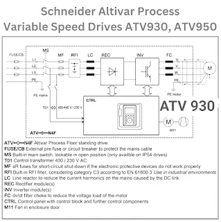
variable speed drives ATV

 Understanding the Working Principle of Variable Speed Drives (VSD) with a Focus on ATV (Altivar) Drives


Variable Speed Drives (VSDs), also known as Adjustable Speed Drives (ASDs) or Variable Frequency Drives (VFDs), are crucial in modern industrial applications for controlling motor speed and improving process control. This article delves into the working princ


iple of VSDs with a particular focus on ATV (Altivar) drives, which are widely recognized for their efficiency and reliability.


 Introduction to Variable Speed Drives


VSDs are electronic devices that control the speed and torque of electric motors by varying the motor input frequency and voltage. This ability to adjust the motor speed is essential in applications where the process requires different speeds at different times, leading to enhanced performance, energy savings, and extended equipment life.


Working Principle of VSDs


The primary components of a VSD include a rectifier, a DC bus, an inverter, and a control unit. Here’s a breakdown of their functions:


1.Rectifier:

 The rectifier converts the incoming AC (Alternating Current) power supply to DC (Direct Current). This stage often uses a diode bridge rectifier.


2. DC Bus:

 The DC bus consists of capacitors that smooth out the DC signal, ensuring a stable and consistent DC voltage is supplied to the inverter.


3. Inverter: 

The inverter is the heart of the VSD, converting the DC voltage back to AC voltage with variable frequency and amplitude. This conversion is achieved using power electronic devices like Insulated Gate Bipolar Transistors (IGBTs).


4. Control Unit:

 The control unit, typically a microcontroller or DSP (Digital Signal Processor), manages the overall operation of the VSD. It controls the switching of the IGBTs in the inverter to produce the desired output frequency and voltage.


How VSDs Control Motor Speed


 speed of a AC motor is determined by a frequency of the AC power supply. By adjusting the frequency of the output voltage, the VSD can control the motor speed. This is done through Pulse Width Modulation (PWM), a technique where the inverter generates a series of voltage pulses at varying widths to simulate a sinusoidal AC waveform. By varying the frequency of these pulses, the VSD adjusts the motor speed accordingly.


 ATV (Altivar) Drives


Altivar drives, manufactured by Schneider Electric, are a popular series of VSDs known for their robust performance, energy efficiency, and advanced control features. These drives are designed to meet the demands of various industrial applications, from simple motor control to complex automation systems.


 Key Features of ATV Drives


1.Energy Efficiency:

 ATV drives are designed to optimize energy consumption by adjusting motor speed to match the required load. This results in significant energy savings, especially in applications like pumps and fans where the load varies over time.


2. Advanced Control: 

Altivar drives offer sophisticated control algorithms, including sensorless vector control and flux vector control, providing precise motor speed and torque control. This is particularly beneficial in applications requiring high dynamic performance and accuracy.


3.User-Friendly Interface:

 ATV drives come with intuitive user interfaces and configuration tools, making them easy to set up and operate. They also feature communication capabilities with various industrial networks, facilitating integration into complex automation systems.


4.Reliability and Durability: 

Built to withstand harsh industrial environments, Altivar drives offer high reliability and long service life, reducing downtime and maintenance costs.


 Applications of ATV Drives


Altivar drives are versatile and used in a wide range of applications, including:


HVAC Systems: 

For controlling fans and pumps to optimize energy use.

Material Handling: 

In conveyors, cranes, and hoists, providing precise speed and position control.

Industrial Processes:

 In mixers, compressors, and extruders, ensuring optimal performance and energy efficiency.


Conclusion


Variable Speed Drives, particularly the Altivar series, play a vital role in modern industrial automation, offering significant benefits in terms of energy efficiency, process control, and equipment longevity. Understanding their working principle helps in appreciating how these devices contribute to the advancements in industrial technology and operational efficiency.

Monday, July 29, 2024

Electric solenoid valve

Electric solenoid valve:


An electric solenoid valve is an electromechanically operated valve used to control the flow of liquids or gases. The key components of a solenoid valve include the solenoid (a coil of wire that generates a magnetic field when electric current passes through it), the plunger or piston, and the valve body.


When the solenoid is energized by an electrical signal, it creates a magnetic field that pulls the plunger or piston towards the center of the coil. This moveing either opens or closes the valve, depending on its design. Solenoid valves can be normally closed (NC) or normally open (NO). In a normally closed valve, the valve remains closed when the solenoid is de-energized and opens when energized. Conversely, in a normally open valve, the valve stays open when de-energized and closes when the solenoid is energized.


Solenoid valves come in various types to suit different applications. Direct-acting solenoid valves operate directly on the valve seat to open or close the valve, making them suitable for low-flow applications. Pilot-operated solenoid valves, on the other hand, use the solenoid to control a pilot valve, which in turn controls the main valve. This design is ideal for high-flow applications as it allows the main valve to be operated with a small solenoid.


The versatility of electric solenoid valves makes them indispensable in many industries. They are widely used in fluid power pneumatic and hydraulic systems, controlling cylinders, fluid power motors, or larger industrial valves. In the HVAC industry, solenoid valves manage the flow of refrigerants. Additionally, they are found in domestic appliances like dishwashers and washing machines to control water flow.


In conclusion, electric solenoid valves are essential components in fluid control systems, offering precise and automated control over the flow of liquids and gases. Their reliability, responsiveness, and versatility make them a preferred choice in numerous industrial and domestic applications.

Sunday, July 28, 2024

programmable logic controller

 Programmable Logic Controller (PLC): Working Principle:


A Programmable Logic Controller (PLC) is an industrial digital computer designed to perform control functions, primarily for manufacturing processes such as assembly lines, robotic devices, or any activity requiring high reliability, ease of programming, and process fault diagnosis. Understanding the working principle of a PLC is crucial for grasping its significance in industrial automation.


Components of a PLC

1. Central Processing Unit (CPU):

The brain of the PLC, it processes instructions from the control program and manages the data flow.

2.Memory:

 Stores the control program and the data necessary for the PLC to operate. Memory types include RAM for temporary data storage and ROM or EEPROM for permanent storage of the control program.

3. Input/Output (I/O) Modules:

 Interfaces for connecting external devices to the PLC. Input modules receive signals from sensors and switches, while output modules send control signals to actuators like motors and valves.

4. Power Supply:

Provides the necessary electrical power to the PLC and its components.

5. Communication Interfaces:

 Allow the PLC to communicate with other PLCs, computers, and Human-Machine Interfaces (HMIs) for monitoring and control.


 Working Principle

1. Input Scan 

The PLC operation begins with the input scan. During this phase, the PLC checks the status of all input devices connected to it, such as sensors, switches, and other data sources. The input modules convert the analog or digital signals from these devices into a format that the CPU can process.


 2. Program Execution


After scanning the inputs, the PLC executes the control program stored in its memory. This program is typically written in a specialized programming language such as Ladder Logic, Function Block Diagram (FBD), or Structured Text (ST). The CPU reads each instruction in the program sequentially, performs the necessary logic operations, and determines the corresponding outputs based on the input conditions.


For example, a simple control program might involve an if-then logic: if a sensor detects an object, then activate a conveyor belt. The CPU processes this logic and updates the status of the outputs accordingly.


3.Output Scan


Once the program execution is complete, the PLC moves to the output scan phase. In this phase, the CPU sends the updated status to the output modules, which then control the connected actuators. The actuators perform the desired actions, such as turning on a motor, opening a valve, or starting a machine.


4.Housekeeping


The final phase involves housekeeping tasks, such as internal diagnostics, communication with other devices, and updating internal registers. The PLC ensures that all systems are functioning correctly and prepares for the next input scan.


 Scan Cycle


The entire process from input scan to housekeeping is known as the scan cycle. A PLC continuously repeats this cycle, usually within milliseconds, ensuring real-time control of industrial processes. The speed and efficiency of the scan cycle are critical, as they determine the PLC’s ability to respond to changes in the input conditions promptly.


Advantages of PLCs


1. Flexibility:

 PLCs can be reprogrammed to adapt to new processes or changes in production lines without requiring extensive rewiring or hardware modifications.

2. Reliability:

 Designed for harsh industrial environments, PLCs are robust and can operate continuously with minimal downtime.

3. Ease of Programming:

 User-friendly programming languages and interfaces allow engineers to develop and modify control programs quickly.

4. calability:

PLC systems can be expanded by adding more I/O modules, making them suitable for both small-scale and large-scale applications.

5.Integration:

PLCs can easily integrate with other industrial systems and devices, enabling seamless automation and data exchange.


Applications


PLCs are widely used in various industries, including automotive, food and beverage, pharmaceuticals, and manufacturing. They control processes such as assembly lines, packaging, material handling, and robotic operations. By automating these processes, PLCs improve efficiency, reduce human error, and increase productivity.


Conclusion


The working principle of a PLC revolves around a continuous scan cycle that involves input scanning, program execution, output scanning, and housekeeping tasks. This cycle ensures real-time monitoring and control of industrial processes, making PLCs indispensable in modern automation. Their flexibility, reliability, ease of programming, and integration capabilities make them a preferred choice for industries aiming to enhance operational efficiency and productivity.

Saturday, July 27, 2024

interruptor termommagnetico circuit breakers

interruptor termommagnetico circuit breaker:


 An interrupter termomagnético, commonly known as a thermal-magnetic circuit breaker, is a device designed to protect electrical circuits from damage caused by overloads or short circuits. Its operation relies on two primary mechanisms: thermal protection and magnetic protection. Below, I’ll outline the working principles and functions in more detail.


 Thermal Protection Mechanism


1.Bimetallic Strip: 

At the core of the thermal mechanism is a bimetallic strip, composed of two different metals bonded together. The metals is different coefficients of thermal expansion.

2. Overload Condition: 

When current flows through the circuit breaker, the bimetallic strip heats up due to electrical resistance. Under normal conditions, this heat is minimal. However, during an overload, the current exceeds the breaker's rated capacity, causing the strip to heat up significantly.

3. Bending of the Strip: 

As the strip heats, the metal with the higher expansion coefficient expands more than the other, causing the strip to bend.

4.Tripping Mechanism: 

The bending of the strip eventually reaches a point where it triggers the tripping mechanism, opening the circuit and interrupting the current flow. This prevents the overheating of the circuit and potential fire hazards.


Magnetic Protection Mechanism


1. Electromagnetic Coil:

 The magnetic protection mechanism involves an electromagnetic coil that is activated by high current levels typically associated with short circuits.

2. Magnetic Field: 

When a short circuit occurs, the high current passing through the coil generates a strong magnetic field.

3. Moving Armature: 

This magnetic field pulls a moving armature towards it, which is connected to the tripping mechanism.

4. Rapid Response: 

The magnetic trip is almost instantaneous, providing immediate protection against short circuits by rapidly opening the circuit.


 Coordination Between Thermal and Magnetic Mechanisms

Dual Protection:

 The thermal protection mechanism is slower, responding to prolonged overcurrent conditions, while the magnetic protection is fast-acting, responding almost immediately to short circuits. This dual mechanism ensures comprehensive protection for various types of electrical faults.

Adjustable Settings:

 Many thermal-magnetic circuit breakers allow for adjustable settings, enabling customization of the trip characteristics to match the specific needs of the electrical system they are protecting.


# Advantages of Thermal-Magnetic Circuit Breakers

1.Reliability: 

These breakers are highly reliable, providing consistent protection against overloads and short circuits.

2. Durability:

 They are designed to endure multiple trips without significant wear, ensuring long-term protection.

3.Versatility:

 Available in various sizes and ratings, they can be used in residential, commercial, and industrial applications.

4. Cost-Effective:

 Compared to other types of protection devices, thermal-magnetic circuit breakers are relatively affordable and provide a cost-effective solution for circuit protection.


Applications

Residential Use:

 Protecting household circuits and appliances from overloads and short circuits.

Commercial Buildings: 

Ensuring the safety of electrical installations in offices, retail spaces, and other commercial environments.

Industrial Settings:

 Providing protection for machinery, equipment, and complex electrical systems in factories and other industrial facilities.


 Conclusion

The interrupter termomagnético, or thermal-magnetic circuit breaker, plays a crucial role in maintaining electrical safety. Its dual protection mechanisms efficiently handle both prolonged overloads and sudden short circuits, making it an essential component in a wide range of electrical systems. By understanding its operation and benefits, users can ensure optimal protection for their electrical infrastructure.

Wednesday, July 24, 2024

Differences between isolation and circuit breakers

Both Isolationand circuit breaker are different concept in terms of Electrical Engineering and System Design perspective :


1. Isolation:


Purpose:


To isolate parts of the system to keep them secure, safe and stop a fault from spreading.


Application:


Typically used in order to protect humans against electric shock, restrain the exchange of electrical noise as far by adequate containment and ensure that a live system can be worked on safely.


Example:


Isolation Transformers Galvanic Isolator Switches


2. Circuit Breaker:


-Purpose:


Overcurrent protection device that goes under the category of fuses or its other immunity; Some type of overcurrent correction- It is what disconnects automatically a electric Circuit from an overload, including short circuit_ when accompanied by third-party temperature cues.


Application:


Used extensively in electrical distribution systems to prevent fires and other damage.


Examples:


There are three different types: thermal circuit breakers, magnetic circuit breakers and hybrid circuits.


To sum it up, isolation is concerned with

Tuesday, July 16, 2024

Automatic Transfer Switch (ATS)

 Automatic Transfer Switches (ATS)


An Automatic Transfer Switch (ATS) is a critical component in power management systems, especially where uninterrupted power is essential. ATS is designed to automatically transfer a power load from its primary source to a backup source when it senses a failure or an unacceptable drop in power quality. Here's a comprehensive look at what ATS is, how it works, and its importance.

(ATS)Breaker


 What is an Automatic Transfer Switch (ATS)?


An Automatic Transfer Switch (ATS) is an electromechanical device that switches the load between two power sources, typically between a primary source (such as the utility grid) and a secondary source (such as a generator). The switch ensures continuous power by automatically transferring the load to the backup source during a power outage or when the primary source fails.


How Does an ATS Work?


An ATS operates through a series of steps, ensuring a seamless transition between power sources:


1. Monitoring: 

The ATS continuously monitors the voltage and frequency of both the primary and secondary power sources. It detects any anomalies, such as power loss, under-voltage, over-voltage, or frequency fluctuations in the primary source.


2. Detection:

 When the ATS detects a problem with the primary power source, it sends a signal to start the backup generator. Modern ATS units can also detect when the power quality of the primary source falls below acceptable levels.

3. Transfer: 

Once the backup generator reaches a stable voltage and frequency, the ATS disconnects the load from the primary source and connects it to the backup source. This transfer is typically completed in a matter of seconds, minimizing downtime and ensuring continuous power supply.


4. Re-transfer: 

When  ATS senses that the primary power source has stabilized and returned to normal, it switches the load back from the backup source to the primary source. The generator is then turned off after a cool-down period.


 Types of Automatic Transfer Switches


There are several types of ATS, each suited for different applications and levels of complexity:


1. Open Transition:

 This type of ATS transfers the load with a momentary break in power. It disconnects the primary source before connecting the backup source. This brief interruption is acceptable for non-critical loads but may not be suitable for sensitive equipment.


2. Closed Transition: 

This ATS type provides a seamless transfer with no break in power. It briefly connects both power sources in parallel during the transfer. Closed transition ATS is ideal for critical applications where even a brief power interruption is unacceptable.


3. Soft Load Transition:

 This type allows for a gradual transfer of the load, balancing the load between the primary and secondary sources before completing the transfer. This method reduces stress on the electrical systems and is used in applications requiring high reliability and stability.


4. Bypass Isolation:

 This type allows for maintenance or testing of the ATS without interrupting the power supply. It includes a bypass switch that can isolate the ATS from the load, ensuring uninterrupted power during servicing.


Applications of Automatic Transfer Switches


ATS units are used in various settings where continuous power is crucial, including:


-Hospitals and Healthcare Facilities: 

Uninterrupted power is essential for life-support systems and critical medical equipment.

-Data Centers: 

To prevent data loss and ensure continuous operation of servers and networking equipment.

-Industrial and Manufacturing Plants: 

To maintain production lines and prevent costly downtime.

Commercial Buildings:

 For lighting, elevators, and other essential services.

Residential Homes: 

In areas prone to power outages, to keep critical home systems running.


Importance of Automatic Transfer Switches


The importance of ATS cannot be overstated in environments where continuous power is vital. Some key benefits include:


-Reliability: 

Ensures a reliable power supply by automatically switching to a backup source without human intervention.

Safety:

 Prevents damage to electrical equipment and reduces the risk of power-related hazards.

Efficiency: 

Minimizes downtime and maintains productivity in commercial and industrial settings.

Convenience: 

Provides peace of mind, knowing that power continuity is maintained even during outages.


 Conclusion


Automatic Transfer Switches (ATS) play a crucial role in ensuring continuous power supply in various applications. By automatically switching between primary and backup power sources, ATS units provide reliability, safety, efficiency, and convenience. Whether in hospitals, data centers, industrial plants, or residential homes, ATS units are essential for maintaining power continuity and protecting critical systems from power interruptions.

Minimum Oil Circuit Breakers (MOCB)

 Minimum Oil Circuit Breakers (MOCB)


Definition


A Minimum Oil Circuit Breaker (MOCB) is a type of circuit breaker that uses a minimal amount of oil as an arc-quenching and insulating medium. Unlike bulk oil circuit breakers, which use a large volume of oil, MOCBs are designed to use oil only around the contacts, significantly reducing the amount of oil needed.


 Components of MOCBs


1. Interrupting Chamber:

 Contains the moving and fixed contacts. This chamber is filled with oil to quench the arc formed during the interruption.

2. Contacts:

 Includes the moving contact and the fixed contact. The arc is drawn between these contacts when they separate.

3. Operating Mechanism: 

The mechanical system that operates the opening and closing of the contacts.

4.Insulating Oil:

 A dielectric fluid that acts as both an arc-quenching medium and an insulator. Only a minimal amount of oil is used, hence the name.

5. Tank: 

Houses the interrupting chamber and provides structural support.

MOCB Breaker


 How MOCBs Work


1.Normal Operation: 

In normal conditions, the contacts within the MOCB are closed, allowing current to flow through the circuit.

2. Fault Detection:

 When a fault (such as an overload or short circuit) is detected, the control system signals the MOCB to open.

3. Contact Separation: 

The operating mechanism moves the contacts apart. As the contacts separate, an arc is formed between them.

4. Arc Formation: 

The arc generated between the separating contacts is confined within the interrupting chamber filled with oil.

5. Arc Extinction:

 The oil in the interrupting chamber vaporizes, forming hydrogen gas, which helps quench the arc. The rapid cooling and deionization of the arc path by the oil lead to the extinction of the arc.

6. Isolation:

 Once the arc is extinguished, the circuit is effectively isolated, stopping the current flow and protecting the system.


Advantages of MOCBs


1.Reduced Oil Volume:

 MOCBs use significantly less oil compared to bulk oil  breakers, making them safer and more economical.

2. Effective Arc Quenching:

 The oil provides excellent arc-quenching capabilities, quickly extinguishing the arc and ensuring reliable operation.

3. Compact Design:

 The reduced amount of oil allows for a more compact design, saving space in installations.

4. Improved Safety: 

With less oil, there is a reduced risk of fire and environmental hazards associated with oil handling and disposal.

5.Cost-Effective: 

Lower oil volume translates to reduced maintenance and operational costs.


 Applications of MOCBs


1.Power Distribution:

 Widely used in medium-voltage distribution networks for reliable protection.

2. Industrial Facilities:

 Employed to protect electrical systems and machinery in various industrial settings.

3. Substations:

 Used in substations to manage and protect the electrical power grid.

4. Commercial Buildings:

 Applied in large commercial installations for efficient power distribution and protection.


 Conclusion


Minimum Oil Circuit Breakers (MOCBs) provide an effective and economical solution for interrupting and isolating electrical faults. By using a minimal amount of oil as an arc-quenching medium, MOCBs combine the benefits of efficient arc extinction with a compact and safer design. They are a preferred choice in medium-voltage applications across various industries, ensuring reliable protection and operation of electrical power systems.

SF6 Circuit Breakers

 Understanding SF6 Circuit Breakers.


Definition


SF6 Circuit Breakers use sulfur hexafluoride (SF6) gas as the arc-quenching and insulating medium. SF6 is a potent greenhouse gas, known for its excellent insulating properties and arc-extinguishing capabilities. These circuit breakers are used in high-voltage electrical power systems to protect and control the flow of electric current.

SF6 Circuit Breakers


 Components of SF6 Circuit Breakers


1. SF6 Gas: 

The primary insulating and arc-quenching medium. It has high dielectric strength and excellent arc-extinguishing properties.

2.Contacts:

 Includes fixed and moving contacts that make or break the electrical circuit.

3. Arc Chamber:

 Contains the contacts and the SF6 gas. It is where the arc is formed and extinguished.

4. Operating Mechanism: 

The mechanical system that operates the opening and closing of the contacts.  operated by manually and automatically.

5. Control System:

 Includes protection relays and sensors to detect fault conditions and trigger the breaker operation.


 How SF6 Circuit Breakers Work


1.Normal Operation:

 Under normal conditions, the contacts within the SF6 circuit breaker are closed, allowing current to flow through the circuit.


2.Fault Detection: 

When a fault, such as an overload or short circuit, is detected, the control system sends a signal to the SF6 circuit breaker to operate.


3. Contact Separation: 

The operating mechanism drives the moving contact away from the fixed contact. This separation creates an arc between the contacts.


4. Arc Formation: 

As the contacts separate, an electrical arc is formed between them. The SF6 gas in the arc chamber begins to ionize and form a plasma.


5. Arc Extinction: 

The SF6 gas quickly cools and de-ionizes the arc plasma. The high dielectric strength of the SF6 gas rapidly restores the insulating properties, extinguishing the arc.


6. Cooling and Insulation: 

After extinguishing the arc, the SF6 gas continues to provide excellent insulation between the contacts, preventing further current flow.


7. Reclosing:

 Once the fault is cleared, the contacts can be closed again to restore the normal operation of the circuit.


Advantages of SF6 Circuit Breakers


1.High Insulating Strength:

 SF6 gas has a very high dielectric strength, making it ideal for high-voltage applications.


2.Effective Arc Quenching:


 SF6 gas is highly effective at quenching arcs, ensuring reliable and rapid interruption of fault currents.

3.Compact Design:

 SF6 circuit breakers are more compact and require less space compared to other types of high-voltage circuit breakers.

4.Long Service Life: 

The components of SF6 circuit breakers are less prone to wear and tear, leading to a longer operational life.

5.Low Maintenance: 

The sealed design and properties of SF6 gas result in lower maintenance requirements.


 Applications of SF6 Circuit Breakers


1.High-Voltage Substations:

 Used to protect and control high-voltage equipment such as transformers and generators.

2.Power Distribution: 

Widely used in electrical distribution networks to manage and protect the power grid.

3. Industrial Facilities:

 Employed in heavy industrial settings where high-voltage and high-current interruptions are common.

4. Renewable Energy Plants:

 Used in wind and solar power plants to ensure reliable power distribution and protection.


Conclusion


SF6 Circuit Breakers are crucial for the reliable protection and control of high-voltage electrical power systems. Their use of sulfur hexafluoride gas as an insulating and arc-quenching medium makes them highly effective at handling high currents and voltages. With their numerous advantages, including high insulating strength, effective arc quenching, compact design, long service life, and low maintenance, SF6 circuit breakers are a preferred choice in various industrial, commercial, and power distribution applications.

Bulk Oil Circuit Breakers (BOCB)

 Bulk Oil Circuit Breakers (BOCB)


Definition


A Bulk Oil Circuit Breaker (BOCB) is a type of circuit breaker that uses a large volume of oil as both an insulating and arc-quenching medium. The oil serves to cool and extinguish the electrical arc formed when the circuit breaker operates. BOCBs are primarily used in high-voltage applications due to their ability to handle large currents and voltages.


Components of BOCBs


1. Tank:

 A robust container filled with insulating oil. The tank houses the contacts and arc-quenching mechanisms.

2. Contacts: 

Includes fixed and moving contacts. The electrical arc is formed between these contacts during operation.

3. Arc Control Device:

 Devices such as arc chutes or arc splitters that help control and extinguish the arc.

4. Operating Mechanism: 

The mechanical system that opens and closes the contacts. It can be operated manually or automatically.

5.Insulating Oil:

 A dielectric fluid that serves both as an insulator and an arc-quenching medium. The oil surrounds the contacts and absorbs the energy of the arc.


How BOCBs Work


1.Normal Operation:

 Under normal conditions, the contacts within the BOCB are closed, allowing current to flow through the circuit.


2. Fault Detection: 

When a fault, such as an overload or short circuit, is detected, the control system sends a signal to the BOCB to operate.


3. Contact Separation: 

The operating mechanism drives the moving contact away from the fixed contact. This separation creates an arc between the contacts.


4.Arc Formation: 

As the contacts separate, an electrical arc is formed. This arc is maintained within the oil-filled tank.


5. Arc Extinction: 

The heat generated by the arc causes the surrounding oil to vaporize, producing gases (primarily hydrogen). These gases rapidly expand and cool, extinguishing the arc.


6.Cooling and Insulation: 

The oil also cools the contacts and provides insulation, preventing further current flow after the arc is extinguished.


7.Isolation:

 Once the arc is extinguished, the circuit is isolated, stopping the current flow and protecting the electrical system.


Advantages of BOCBs


1.Effective Arc Quenching: 

The large volume of oil provides excellent arc-quenching capabilities, ensuring reliable interruption of high-current faults.


2.Insulation: 

The oil offers strong insulating properties, helping to prevent electrical breakdowns between the contacts and the tank.


3. Cooling: 

The oil helps dissipate the heat generated during the arc, protecting the breaker components from damage.


Applications of BOCBs


1.High-Voltage Substations:

 Used to protect transformers, generators, and other critical components in high-voltage substations.

2.Industrial Plants: 

Employed in heavy industrial settings where high voltage and current interruptions are common.

3.Power Distribution: 

Widely used in the distribution networks to manage and protect the power grid.


 Conclusion


Bulk Oil Circuit Breakers (BOCBs) are essential components in electrical power systems, offering reliable protection and control for high-voltage applications. Their use of a large volume of oil for both insulation and arc quenching makes them effective at handling high currents and voltages, ensuring the safety and stability of power networks.

Vacuum Circuit Breakers (VCB)

Vacuum Circuit Breakers (VCB)


 Definition

A Vacuum Circuit Breaker (VCB) is an electrical device used to protect and control electrical power systems. It operates by interrupting the flow of current during a fault condition.  The "vacuum" in VCB refers to the vacuum medium used as the arc extinction chamber. When the circuit breaker opens, the contacts separate in a vacuum, and the arc formed between them is quickly extinguished, preventing current flow and protecting the circuit.

VCB Breakers


 Components of a VCB


1.Vacuum Interrupter:

 The core component where the arc extinction takes place. It contains the fixed and movable contacts enclosed in a vacuum-tight chamber.

2. Contacts: 

The fixed and moving contacts that make or break the electrical circuit. These contacts are housed within the vacuum interrupter.

3. Operating Mechanism: 

The mechanical system that opens and closes the contacts.


4. Insulating Medium:

 The vacuum acts as the insulating medium, ensuring that there is no current flow between the contacts once the arc is extinguished.

5.Control System:

 Includes protection relays and sensors to detect fault conditions and trigger the breaker operation.


How VCBs Work


1. Normal Operation: 

In normal conditions, the VCB contacts are closed, allowing current to flow through the circuit.

2. Fault Detection.

 When a fault is detected (such as an overload or short circuit), the control system signals the VCB to open.

3.Contact Separation:

 The operating mechanism drives the moving contact away from the fixed contact.

4. Arc Formation: 

As the contacts separate, an arc forms between them.

5. Arc Extinction:

 The vacuum within the interrupter quickly extinguishes the arc, as there are no gases or other mediums to sustain it.

6. Isolation:

 Once the arc is extinguished, the circuit is effectively isolated, stopping the current flow and protecting the system.


Advantages of VCBs


1.High Insulating Strength: 

The vacuum has excellent insulating properties, making VCBs suitable for high-voltage applications.

2. Rapid Arc Extinction: 

The vacuum environment ensures rapid arc extinction, enhancing the reliability and safety of the circuit breaker.

3.Long Life:

 VCBs have a longer operational life compared to other types of circuit breakers because there is minimal wear and tear on the contacts.

5. Compact Design:

 VCBs are generally more compact and lightweight compared to other high-voltage breakers, making them suitable for space-constrained installations.


Applications of VCBs


1. Power Plants:

 To protect generators and transformers.

2.Substations:

  in high-voltage substations to manage and protect the power grid.

3.Industrial Facilities: 

For protecting heavy machinery and ensuring the safety of electrical systems.

4.Commercial Buildings:

 Used in large commercial installations to ensure reliable power distribution and protection.


Conclusion


Vacuum Circuit Breakers (VCBs) are essential components in modern electrical power systems, offering reliable protection and control. Their ability to quickly extinguish arcs in a vacuum makes them ideal for high-voltage applications, ensuring safety and efficiency. With their numerous advantages, including low maintenance, long life, and compact design, VCBs continue to be a preferred choice in various industrial, commercial, and power distribution applications.

Monday, July 15, 2024

Air Circuit Breakers (ACBs)

 Understanding Air Circuit Breakers (ACBs)


An Air Circuit Breaker (ACB) is a critical component in electrical distribution systems, designed to protect electrical circuits from damage caused by overcurrent, short circuits, or electrical faults. ACBs are primarily used in low voltage applications, typically below 450 volts, and they play a pivotal role in ensuring the safety and reliability of electrical systems in industrial, commercial, and residential settings.


 How ACBs Work


ACBs operate by interrupting the flow of current in the event of a fault. When a fault occurs, the circuit breaker detects the abnormal condition and triggers its mechanism to open the circuit. Unlike other types of circuit breakers that use oil or vacuum as the interrupting medium, ACBs utilize air. The air serves as the arc extinguishing medium, cooling and de-ionizing the arc that forms when the contacts within the breaker separate

ACBs Circuit Breaker 


 Components of ACBs

1. Frame: 

The frame houses all the internal components and provides structural support.

2. Contacts:

 These are the conductive parts that open and close to either interrupt or allow the flow of current.

3. Arc Chutes:

 Arc chutes are chambers designed to cool and extinguish the arc formed during the interruption process.

4. Operating Mechanism: 

This includes the trip unit, which detects fault conditions, and the actuator, which physically opens the contacts.

5. Trip Unit:

 The trip unit is the brain of the ACB. It monitors the current flowing through the circuit and initiates the trip process when it detects anomalies such as overcurrent or short circuits.


 Advantages of ACBs


ACBs offer several advantages that make them a preferred choice in many applications:


1. High Interruption Capacity:

 ACBs can handle large fault currents, making them suitable for applications where high reliability and safety are required.

2. Flexibility:

 They are available in a wide range of ratings and configurations, allowing for customization to meet specific requirements.

3. Ease of Maintenance: 

ACBs are relatively easy to maintain and inspect. Their design allows for straightforward replacement of parts, minimizing downtime during maintenance activities.

4. Reusability: 

Unlike some other types of circuit breakers, ACBs can often be reset and reused after a trip, provided there is no significant damage.


Applications of ACBs


ACBs are used in a variety of settings, including:


1.Industrial Plants: 

In factories and manufacturing plants, ACBs protect heavy machinery and electrical equipment from damage caused by electrical faults.

2. Commercial Buildings:

 In office buildings, shopping malls, and other commercial establishments, ACBs ensure the safety of electrical systems, protecting both the infrastructure and occupants.

3. Residential Areas: 

Although less common in residential settings, ACBs are sometimes used in large residential complexes or where high electrical loads are present.

4. Utility Systems: 

ACBs are also utilized in utility systems for protecting transformers, generators, and other critical infrastructure.


Conclusion


In summary, Air Circuit Breakers are indispensable components in modern electrical distribution systems, offering robust protection against electrical faults. Their high interruption capacity, flexibility, ease of maintenance, and reusability make them a reliable choice for a wide range of applications. As technology advances and electrical systems become more complex, the role of ACBs in ensuring electrical safety and reliability will continue to be of paramount importance.

Different between circuit breakers and isolator

 Circuit breakers and isolators are both electrical devices used in power systems, but they have different functions and are used for distin...