Showing posts with label Basic electrical knowledge. Show all posts

Monday, September 16, 2024

Why electricity kill the human?

 Why 
Electricity kill the humans:

 because it disrupts the normal functioning of vital organs, particularly the heart, muscles, and nervous system. The severity of the effect depends on factors such as the current, duration of exposure, and the path electricity takes through the body. Here’s how electricity affects the body:


1. Interference with the Heart (Ventricular Fibrillation)

 Electric shock

 can disrupt the electrical signals that control the heartbeat, potentially causing ventricular fibrillation

This is an irregular and often fatal heart rhythm that prevents the heart from pumping blood effectively, leading to cardiac arrest and death if untreated.


 2.Muscle Contraction and Paralysis

   - Electric current passing through muscles causes them to contract involuntarily. With higher currents, muscles may "lock up," making it impossible to let go of the source of the shock. This prolonged exposure increases the risk of severe injury or death.

   - For high currents, muscles may contract so violently that they can cause broken bones or internal injuries.


 3. Nervous System Damage

   - The nervous system, which communicates using electrical impulses, can be severely disrupted by electric current. This interference can lead to loss of muscle control, paralysis, or even unconsciousness.


4. Burns and Tissue Damage

   High-voltage electric shocks can cause severe burns at both the point of entry and exit, as well as along the path the current travels inside the body. This can lead to internal damage, organ failure, or death due to thermal injuries.

   - Internal tissue damage may not always be visible immediately, but electric currents can destroy blood vessels, nerves, and organs.


 5. Respiratory Arrest

 If electricity passes through the chest, it can interfere with the diaphragm, which controls breathing. This may result in respiratory arrest stopping breathing, and leading to suffocation if not treated promptly.


Factors Affecting the Severity of Electric Shock:

Current (Amperage): 

Even low currents (as low as 10 mA) can cause harmful effects. Currents above 100 mA can be fatal.

Voltage:

 High voltage increases the likelihood of injury, but even household voltages (120V or 230V) can be lethal under the right conditions.

Path through the Body

If the current passes through vital organs (e.g., from hand to hand or hand to foot), the risk of death increases.

Duration: 

The longer the exposure to the current, the more severe the injury.

Resistance:

 The body’s resistance (mainly skin) affects how much current flows through. Wet or damaged skin reduces resistance, allowing more current to pass.


Electricity is particularly dangerous because it can cause sudden, catastrophic effects in the body, often without much warning.

Sunday, September 15, 2024

Which is more dangerous AC or DC & why?

 Both AC (Alternating Current) and DC (Direct Current) can be dangerous, but AC is generally considered more dangerous to humans than DC for several reasons:


1. Effect on the Heart:

   AC can cause 

ventricular fibrillation a dangerous and irregular heartbeat, even at lower currents (as low as 100-300 mA at 60 Hz). This is because AC repeatedly passes through zero, making it more likely to interfere with the natural rhythm of the heart.


  DC tends to cause muscle contractions, and while it can still be dangerous, it often causes the victim to be "thrown" away from the current source due to the strong muscle contraction, whereas AC may cause muscles to "freeze" and prolong the exposure.


2. Frequency Factor:

   - The standard household AC frequency (50-60 Hz) is particularly dangerous because it's close to the natural frequency of the human heart, increasing the likelihood of fibrillation.


3. Perception and Let-Go Threshold:

   - AC has a lower 

let-go threshold meaning that at certain currents, a person may not be able to let go of the conductor due to involuntary muscle contractions. With DC, while still dangerous, the let-go threshold is higher.


4. Peak Voltage:

   - For the same root-mean-square (RMS) voltage, AC reaches a peak voltage that is about 1.414 times higher than DC. For instance, 230V AC has a peak voltage of about 325V, which can cause more severe electric shock compared to 230V DC.


However (DC) can also be highly dangerous, especially at high voltages (e.g., electric cars, batteries in certain applications). Both AC and DC require careful handling and appropriate safety measures.

Saturday, September 14, 2024

Good grounding resistance value

 A good ground resistance value typically depends on the specific application, but in general:


-For residential and commercial grounding systems

 a resistance value of 5 ohms or lessis often recommended.

For critical systems

 like substations, communication towers, and sensitive electronics, the target is usually 1 ohm or less to ensure a reliable grounding system.


Lower resistance values ensure better protection against electrical faults and surges, providing a safer and more stable system. However, the actual required value can vary depending on factors like soil composition, moisture levels, and safety standards specific to the region or industry.

Friday, September 13, 2024

Definition of electricity

 Wat is electricity 

Electricity is a form of energy resulting from the movement or flow of electric charges, typically electrons. It can be generated through various means, such as chemical reactions (as in batteries), mechanical movement (as in generators), or solar energy (as in solar panels).


There are two main types of electricity:


1. Static Electricity: 

This occurs when there is a buildup of electric charges on the surface of a material. It doesn't flow like current electricity but can discharge, as seen in static shocks.


2.Current Electricity: 

This is the flow of electric charges through a conductor, such as a wire. It can be direct current (DC), where the charges flow in one direction, or alternating current (AC), where the flow of charges changes direction periodically.


Electricity is used to power devices, machines, and lighting, and is essential in modern life for communication, transportation, and more.

Thursday, September 12, 2024

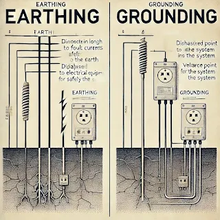
Definition of earthing and grounding

 Definition of earthing and grounding

The terms "earthing" and "grounding" are often used interchangeably, but they have subtle differences based on their usage in electrical systems:


1.Earthing:


   Definition: 

Earthing refers to the physical connection of electrical equipment or systems to the earth's conductive surface, typically through a conductor.

   Purpose:

 The main purpose of earthing is to protect humans and equipment from electrical shocks by providing a path for fault currents to flow directly into the ground.

   Usage:

 Commonly used in British and European standards.

   Application: 

Earthing is specifically used for connecting the non-current carrying parts of the equipment (like the metal casing) to the earth.


2. Grounding:

   Definition:

 Grounding refers to connecting electrical circuits to a reference ground, usually the earth, but it can also refer to connecting to a common point like the chassis of equipment.

   Purpose:

 Grounding is done to ensure the proper functioning of the electrical system by maintaining a reference voltage level, and it helps in stabilizing voltage during faults or surges.

   Usage: 

More commonly used in American standards.

   Application: 

Grounding usually involves the current-carrying parts of the system, such as the neutral wire in an AC circuit.


Key Difference:

 While both terms involve connections to the earth, earthing is focused on safety and preventing electric shocks, whereas grounding ensures system stability and proper functioning.

Monday, September 9, 2024

Different between VA and AH

 The terms "VA" (Volt-Ampere) and "Ah" (Ampere-hour) are used to describe different aspects of electrical systems, particularly batteries and power supplies:


1. VA (Volt-Ampere):

   - VA is a unit of apparent power, used primarily in alternating current (AC) systems like UPS (Uninterruptible Power Supplies).

   - It indicates the capacity of a power supply or UPS, representing the combination of voltage (V) and current (A) the device can handle.

   - It helps to determine how much power the system can supply to connected equipment but doesn't directly indicate how long it will last.


2. Ah (Ampere-hour):

   - Ah is a unit of battery capacity, indicating how much charge a battery can store.

   - It represents the amount of current a battery can supply over a specific time, e.g., a 10Ah battery can deliver 10 amps for one hour or 1 amp for 10 hours.

   - It is directly related to the battery’s runtime and storage capacity, showing how long it can provide power to a load.


**Key Difference**:

- VA measures power capacity in AC systems, while Ah measures battery capacity and energy storage in DC systems. They are not directly interchangeable as they serve different purposes in electrical calculations.

Calculations of va and ah

1. Calculating VA (Volt-Ampere)


The formula for calculating VA is:


{VA} = \{Voltage} (V) \times \{Current} (A)

\]


Example Calculation:

If a device operates at 230V and draws 5A of current, the VA is calculated as:


{VA} = 230V \times 5A = 1150 \,{VA}


This means the device requires an apparent power of 1150 VA to operate.


 2. Calculating Ah (Ampere-hour)


The formula for calculating Ah is:


{Ah} = \frac{Current} (A) \times \{Time} (h)}{Load Efficiency Factor}}

\]


For a basic calculation (assuming 100% efficiency):


{Ah} = \text{Current} (A) \times \{Time} (h)

\]


Example Calculation:

If a battery provides 10A for 3 hours, the Ah is calculated as:


\[{Ah} = 10A \times 3h = 30 \,{Ah}

\]


This means the battery can deliver 10 amps of current continuously for 3 hours before running out of charge.


Converting VA to Ah (Approximate Conversion)


For UPS systems and batteries, VA and Ah are sometimes used interchangeably for practical reasons, though they measure different things. To roughly convert VA to Ah for battery backup calculations:


\[{Ah} \approx \frac{VA} \times \{Backup Time (hours)}}{Battery Voltage}}

\]


Keep in mind this conversion is an approximation, as it depends on factors like power factor, efficiency, and actual load.


Example Calculation:

For a 1200 VA UPS running on a 12V battery for 2 hours:


{Ah} \approx \frac{1200 \, {VA} \times 2 \,{hours}}{12V} = 200 \,{Ah}

\]


This means you would need a battery of around 200 Ah to provide power for 2 hours at 1200 VA. 


Let me know if you need a more specific calculation or further explanation!

Saturday, September 7, 2024

Different between electrical and electronic

 The terms "electrical" and "electronics" are often used interchangeably, but they refer to different areas of technology:


1.Electrical:

   Focus

Deals with the study, design, and application of systems and devices that use large-scale electrical power. 

  Applications:

 Includes power generation, transmission, distribution, and the functioning of devices like motors, generators, transformers, and power lines.

  Components

Involves larger, higher power components such as conductors, insulators, switches, and circuit breakers.

   Energy Flow:

 Primarily concerned with the flow of electrical energy, often in the form of alternating current (AC).


2. Electronics:

  Focus:

 Focuses on the design and use of smaller-scale components that control the flow of electrons, primarily for processing information or signal control.

   Applications:

 Includes devices such as computers, smartphones, radios, televisions, and other digital and analog systems.

   Components:

 Uses smaller, low-power components like transistors, diodes, integrated circuits (ICs), capacitors, and resistors.

   Energy Flow:

 Typically involves direct current (DC) and deals with controlling electrical signals rather than large-scale power.


In summary, electrical engineering deals with the generation and distribution of power, while electronics focuses on manipulating and processing information through electrical signals.

Friday, August 30, 2024

Coaxial cables

Coaxial cables

Coaxial cables are designed with high levels of insulation to protect the signal integrity and ensure efficient transmission, especially for high-frequency signals. The construction of a coaxial cable includes several layers of insulation that each serve a specific purpose:

1. Inner Conductor:

   Material:

 Typically made of copper or copper-clad steel.

   Function:

 Carries the signal. It is at the core of the cable.


2. Dielectric Insulation:

   Material:

 Made of a non-conductive material such as polyethylene, Teflon, or foam.

   Function:

This layer insulates the inner conductor and keeps it separate from the outer conductor (shield). It also plays a key role in determining the cable's impedance and minimizing signal loss.


 3.Outer Conductor (Shield):

   Material:

 Typically made of braided copper or aluminum, or sometimes a combination of a metallic foil and braid.

   Function:

Acts as a shield to protect the inner conductor from electromagnetic interference (EMI) and radio frequency interference (RFI). It also serves as a return path for the signal in some applications.


4.Outer Insulation (Jacket):


   Material:

 Made from a durable plastic such as PVC, polyethylene, or Teflon.

   Function:

Provides mechanical protection to the cable, shielding it from environmental factors like moisture, chemicals, and physical wear and tear. This layer also adds another level of electrical insulation.


 High Insulation Characteristics:

Shielding Efficiency:
 The combination of the outer conductor (shield) and the outer insulation ensures minimal signal leakage and high resistance to interference.

Dielectric Quality:

 The dielectric material's quality is crucial for maintaining the signal's speed and reducing attenuation (signal loss).

Environmental Protection:

 The outer jacket, especially in high-grade coaxial cables, is often designed to resist UV radiation, extreme temperatures, and physical stress, ensuring the cable remains effective in harsh environments.

Applications:

Telecommunications:

 Used for transmitting television, internet, and telephone signals.

Radio Frequency (RF) Applications:

 Used in antennas, transmitters, and receivers.

Video Surveillance:

 Often used in CCTV systems to transmit video signals.

Medical Equipment:

 Used in sensitive devices where signal integrity is crucial.


High insulation in coaxial cables is essential to maintain signal quality over long distances and in environments with potential interference, making them ideal for various communication and signal transmission applications.

Friday, August 16, 2024

Stones in switchyard

 way are stones layed in switchyard:

Stones, often called gravel or ballast, are laid in switchyards (electrical substations) for several important reasons:


1. Insulation:

 Stones provide an insulating layer to prevent step and touch potential, reducing the risk of electrical shock to personnel. This is crucial in high-voltage environments where grounding can be a significant safety concern.


2. Drainage:

 Stones facilitate good drainage, preventing water from accumulating around electrical equipment, which can cause corrosion or short circuits.


3. Weed Control:

The stones help prevent the growth of vegetation, which can obstruct access to equipment and create fire hazards.


4.Stability:

The gravel bed provides a stable surface for heavy electrical equipment, reducing the risk of movement or settling.


5.Fire Prevention:

Stones are non-flammable, reducing the risk of fire spreading within the switchyard, especially if there's a short circuit or equipment failure.


These benefits make gravel an essential part of switchyard design, enhancing safety, functionality, and maintenance.

Sunday, July 14, 2024

capacitor block the DC and passes the AC

 Capacitors have the unique property of blocking direct current (DC) while allowing alternating current (AC) to pass through them. This behavior can be understood through both the physical structure and the electrical properties of capacitors:


- A capacitor connection of two plates separated by an insulating material called the dielectric. When a voltage is applied across the plates, an electric field is established, and charge accumulates on the plates.


 Electrical Properties:


 For DC (Direct Current):

- Constant Voltage:

 When a DC voltage is applied, it creates a constant electric field in the capacitor. Initially, current flows as the capacitor charges up.

-Charging Phase: 

During this phase, electrons accumulate on one plate, creating a positive charge on the other plate due to the electric field across the dielectric.

- Fully Charged State: 

Once the capacitor is fully charged, the voltage across it equals the applied DC voltage, and no further current flows through the circuit. The capacitor now acts as an open circuit for DC, blocking any continuous flow of current.


For AC (Alternating Current):


Changing Voltage: 

AC voltage continuously changes its polarity and magnitude over time, typically in a sinusoidal manner.

Charging and Discharging: 

Due to the alternating nature of AC, the capacitor continually charges and discharges as the voltage changes. When the AC voltage increases, the capacitor charges in one direction. When the voltage decreases or reverses, the capacitor discharges and then charges in the opposite direction.

Current Flow:

 This continuous charging and discharging process allows current to flow through the circuit. The capacitor effectively passes AC by responding to the changing voltage, allowing alternating current to move through while still blocking any steady-state DC component.


Mathematical Explanation:

Impedance:

 The opposition that a capacitor presents to AC is called capacitive reactance (Xc), given by the formula:

  \[

  Xc = \frac{1}{2\pi fC}

  \]

  where \(f\) is the frequency of the AC signal and \(C\) is the capacitance.

Frequency Dependency:

 For DC (where \(f = 0\)), the capacitive reactance \(Xc\) is infinite, meaning no current flows. For AC, as the frequency \(f\) increases, \(Xc\) decreases, allowing more current to pass through the capacitor.


In summary, a capacitor blocks DC because once it is fully charged, it stops allowing current to flow, behaving like an open circuit. However, it passes AC because the continuous change in voltage causes the capacitor to charge and discharge, allowing alternating current to flow through.

How to check IP code

 To check the IP (Ingress Protection) code of a device or equipment, follow these steps:


1. Consult the Product Documentation:


   - Check the user manual, datasheet, or product specification sheet provided by the manufacturer. The IP code is usually listed in the technical specifications section.


2. Look for Markings on the Device.

   - Many devices have their IP rating marked directly on the product casing or label. Look for the IP code on the back, bottom, or side of the device.


3. Manufacturer’s Website.

   - Visit the manufacturer's official website and search for the product. The website often provides detailed specifications, including the IP rating.


4. Contact Customer Support.


   - If the IP code is not readily available, contact the manufacturer's customer support for information.


5. Third-Party Certification:


 Check for certification marks or labels that might indicate the IP rating.


 Understanding the IP Code:


The IP code consists of the letters "IP" followed by two digits and sometimes an additional letter. Here's a quick guide to interpreting the code:


First Digit (Protection against Solid Objects):

  - 0: No protection

  - 1: >50 mm (hands)

  - 2: >12.5 mm (fingers)

  - 3: >2.5 mm (tools, thick wires)

  - 4: >1 mm (most wires, screws)

  - 5: Dust protected (limited ingress)

  - 6: Dust tight (no ingress)


Second Digit (Protection against Liquids):

  - 0: No protection

  - 1: Vertically dripping water

  - 2: Sprays up to 15° from vertical

  - 3: Sprays up to 60° from vertical

  - 4: Water splashes from any direction

  - 5: Low-pressure water jets

  - 6: High-pressure water jets, heavy seas

  - 7: Immersion up to 1 meter

  - 8: Continuous immersion

  - 9K: High-pressure, high-temperature water jets


 Example IP Codes:
   IP67:

 Fully protected against dust (6) and can withstand immersion in water up to 1 meter for a specified time (7).

IP55:

 Dust protected (5) and protected against low-pressure water jets from any direction (5).

IP code chart 

Understanding these codes helps you choose the right device for specific environmental conditions, ensuring it meets the necessary protection standards.

Saturday, July 13, 2024

How to stop electrical fire

How to stop electrical fire 


 Stopping an electrical fire requires immediate action and safety measures. Here are the steps to effectively handle an electrical fire:


1.Cut the Power

 Turn off the Power: 

If safe to do so, disconnect the electricity by turning off the main power switch or circuit breaker. This reduces the risk of electrical shock and prevents the fire from spreading.

  Unplug Devices.

 If the fire is originating from a particular device and it’s safe, unplug it.


 2. Do Not Use Water.

  Water is Conductive: 

Using water can cause electrical shock and exacerbate the fire. Avoid using water on electrical fires at all costs.


 3. Use a Fire Extinguisher

   Class C Fire Extinguisher: 

Use a fire extinguisher rated for electrical fires (Class C). These extinguishers use non-conductive chemicals to douse the flames.

 Proper Technique: 

Aim the nozzle at the base of the fire, squeeze the handle, and sweep from side to side.


 4. Call Emergency Services

  Emergency Response: 

Dial emergency services (e.g., 00) for professional assistance, especially if the fire is large or uncontrollable.


5. Evacuate if Necessary.

   Safety First: 

If the fire cannot be contained, evacuate the area immediately and ensure everyone is at a safe distance. Wait for the fire department to handle the situation.


 6. Use a Fire Blanket

   Smother the Flames:

 If the fire is small, a fire blanket can be used to smother the flames. Place the blanket over the fire to cut off its oxygen supply.


 7. Preventive Measures

   Install Smoke Detectors:

 Ensure smoke detectors are installed and functioning to provide early warning of fire.

Regular Maintenance: 

Regularly check and maintain electrical wiring, outlets, and appliances to prevent potential hazards.

  Avoid Overloading Circuits:

 Do not overload electrical outlets or circuits. Use power strips with surge protectors.


  Turn Off Power: 

Turn off the source of electricity before providing aid.

  Cool the Burn:

 Use cool, running water to cool burns but avoid ice or very cold water.

  Seek Medical Help:

Call emergency services for serious burns or if the person is unconscious

Important Tips

 Know Your Extinguishers.

 Familiarize yourself with the location and operation of fire extinguishers in your home or workplace.

 Have an Emergency Plan:

 Ensure everyone in the household or workplace knows the emergency plan and evacuation routes.


By following these steps, you can effectively manage and stop an electrical fire while ensuring the safety of everyone involved.

Monday, July 8, 2024

Cable sizes and calculations

 To check the size of electrical wires, you can use several methods to determine the gauge or diameter of the wire. Here’s a step-by-step guide:


 1. Visual Inspection

   -Wire Markings:

 Look for printed markings on the wire insulation. Manufacturers often print the wire gauge size directly on the wire.

   Gauge Tool: 

Use a wire gauge tool, which has notches corresponding to different wire sizes. Insert the wire into the notches until you find the one that fits snugly.


2. Measurement with a Caliper

  Prepare the Wire: 

If the wire is insulated, strip a small section of insulation to expose the bare wire.

  Measure Diameter:

Use a caliper to measure the diameter of the bare wire.

   Convert Diameter to Gauge.

 Use a wire gauge conversion chart to determine the gauge size based on the measured diameter.


3. Comparing to Known Gauges

   Known Samples: 

Compare the wire to known wire gauges. This method is useful if you have a set of wires of known sizes for comparison.

  Wire Gauge Chart:

 Use a chart that shows wire gauges along with their corresponding diameters and cross-sectional areas.


 4. Multimeter Resistance Measurement

   Set Up Multimeter: 

Set the multimeter to measure resistance (ohms).

  Measure a Length: 

Measure a known length of the wire (e.g., 1 meter or 1 foot).

   Calculate Resistance:

 Measure the resistance of the wire over that length. Use the resistance value along with wire resistance tables to determine the gauge. This method is less common and requires knowledge of wire resistance per unit length.


Safety Tips

   - Ensure the wire is not connected to any power source before measuring.

   - Wear appropriate safety gear, such as gloves and goggles, if cutting or stripping wire.


 Example Chart for Wire Gauge and Diameter

   18 AWG: 1.02 mm diameter

   16 AWG: 1.29 mm diameter

   14 AWG: 1.63 mm diameter

   12 AWG: 2.05 mm diameter

   10 AWG: 2.59 mm diameter


Electrical wire sizes come in a range of standardized gauges, with the most common system in the United States being the American Wire Gauge (AWG) system. Here are the typical sizes and some of their common uses:

How meny sizes for wire

 Standard AWG Sizes

1. 4/0 (0000) AWG: 

Used for very heavy electrical loads, such as large industrial machines.

2. 3/0 (000) AWG:

 Used in large industrial applications.

3. 2/0 (00) AWG: 

Used for heavy-duty applications, such as large battery banks and industrial installations.

4. 1/0 (0) AWG: 

Used for high-current applications, including large motor and battery connections.

5. 1 AWG:

 Used for large electrical installations and heavy-duty cables.

6. 2 AWG: 

Used for large electric motors and heavy-duty power distribution.

7. 4 AWG: 

Used in large power distribution, electric furnaces, and heavy-duty installations.

8. 6 AWG: 

Used in residential and commercial buildings for large appliances and sub-panels.

9. 8 AWG: 

Used for electric ovens, large air conditioners, and similar heavy-duty appliances.

10. 10 AWG: 

Used for water heaters, air conditioners, and heavy-duty circuits.

11. 12 AWG: 

Commonly used for residential wiring of outlets, light fixtures, and small appliances.

12. 14 AWG:

 Commonly used for residential lighting circuits and light-duty outlets.

13. 16 AWG:

 Used for extension cords, lamp cords, and light-duty power cables.

14. 18 AWG: 

Used for smaller devices, lamp cords, and signal wiring.

15.20 AWG: 

Used for control circuits and low-power signaling.

16. 22 AWG: 

Used for small electronics and low-voltage signaling.

17. 24 AWG: 

Used for data cables, telephone wires, and small electronic devices.

18. 26 AWG:

 Used for data cables, small electronic circuits, and delicate wiring.

19. 28 AWG:

 Used for very small electronic devices and fine wiring.

20. 30 AWG: 

Used for very fine electronic work, such as PCB wiring and delicate circuits.


Metric Wire Sizes
Outside the United States, wire sizes are often measured in square millimeters (mm²) rather than AWG. Some common metric sizes include:


1. 0.5 mm²

2. 0.75 mm²

3. 1.0 mm²

4. 1.5 mm²

5. 2.5 mm²

6. 4.0 mm²

7. 6.0 mm²

8. 10.0 mm²

9. 16.0 mm²

10. 25.0 mm²


Selecting the Right Wire Size

The choice of wire size depends on several factors:

-Current Load:

 Higher currents require thicker wires.

Voltage Drop:

 Longer distances may require larger wires to reduce voltage drop.

Environmental Conditions:

 Temperature and installation environment can affect wire performance.


By understanding these sizes and their typical uses, you can choose the appropriate wire for your electrical projects.

Friday, July 5, 2024

Safe Tools for Electrician

Safe Tools for Electricians

Electricians require specific tools designed to ensure safety and efficiency while working with electrical systems. Here is a list of safe tools commonly used by electricians, along with some safety features to look for:


 1. Insulated Screwdrivers

 Insulated handles rated for 1,000 volts to protect against electrical shock.

   Types: 

Flat-head, Phillips, and specialty screwdrivers for different types of screws and terminals.


 2. Voltage Tester

Non-contact voltage testers are particularly safe as they detect voltage without direct contact with wires.

   3.Multimeter.

 CAT III or CAT IV rating for safe use on different types of electrical Measures voltage, current, and resistance to troubleshoot and verify electrical circuits. 


5. Pliers (Lineman, Needle-Nose, and Side-Cutting)


   Lineman pliers for twisting wires, needle-nose pliers for accessing tight spaces, and side-cutting pliers for cutting wires.

 6. Circuit Tester.

  Insulated probes to prevent electrical shock.

 Tests for continuity and verifies the presence of electrical current in circuits.

7. Fish Tape.

Non-conductive fish tape (made of fiberglass) to prevent electrical shock.

 Pulls wires through conduit or walls.

 8. Conduit Bender

   Handles with non-slip grips for secure handling.Bends conduit pipes to fit electrical wiring in different configurations.

9.Cable Cutters.

Insulated handles to prevent electrical shock and ensure a firm grip.

 Cuts through electrical cables cleanly and efficiently.

 10.Circuit Breaker Finder.

    Designed to work without needing direct contact with live wires.


 Personal Protective Equipment (PPE)

Gloves: Protect against electrical shock when handling live wires or equipment.

Safety Glasses:

 Protect eyes from debris, sparks, and accidental splashes.

Arc Flash Clothing:

 Protects against burns from arc flash incidents.

Hard Hat:

 Protects the head from impacts and falling objects.

Safety Boots: 

Provide protection against electrical hazards and shock. 

Using these safe tools and following best practices will help electricians perform their tasks efficiently while minimizing the risk of accidents and injuries.

Electrical Maintenance tools

Electrical Maintenance tools 


 1. Planning and Preparation


 Develop a Maintenance Schedule: Create a detailed schedule for regular maintenance tasks based on manufacturer recommendations, usage patterns, and regulatory requirements.


 Gather Documentation


 Collect and review all relevant documentation, including electrical schematics, maintenance logs, and equipment manuals.

 This includes de-energizing equipment, locking out/tagging out (LOTO), and wearing appropriate personal protective equipment 


 Visual Inspection: 

Perform a thorough visual inspection of electrical equipment and systems to identify any signs of wear, damage, or overheating.

 - **Thermal Imaging**: Use thermal imaging cameras to detect hot spots that may indicate potential issues like overloaded circuits or loose connections.

 Electrical Testing: 

Conduct various tests such as insulation resistance testing, continuity testing, and circuit breaker testing to assess the condition of electrical components.

 Load Testing:

 Perform load tests to ensure that electrical systems can handle their expected load without issues.


 3. Cleaning and Lubrication

 Clean Components: 

Remove dust, dirt, and other contaminants from electrical components, panels, and enclosures using appropriate cleaning methods and materials.

 Lubricate Moving Parts

 Apply lubricants to moving parts such as switches and circuit breakers to ensure smooth operation and prevent wear.


 4. Tightening and Securing Connections


 Check Connections:

 Inspect all electrical connections, including terminals, plugs, and sockets, for tightness and secure any loose connections.

 Torque Specifications.

 Use a torque wrench to tighten connections to the manufacturer’s recommended specifications to prevent over-tightening or under-tightening.


 5. Component Replacement

 -Identify Worn Components:

 Replace any worn, damaged, or obsolete components with new ones that meet the manufacturer’s specifications.

 Upgrade Components Consider upgrading components to newer, more efficient, or more reliable versions where appropriate.


 6. Functional Testing


 Operational Checks: 

After maintenance, perform functional tests to ensure that all systems and components are operating correctly.

 -Safety Checks: 

Verify that all safety devices, such as ground fault circuit interrupters (GFCIs) and emergency shut-offs, are functioning properly.


 7. Documentation and Reporting


 Update Maintenance Logs

 Record all maintenance activities, including inspections, tests, repairs, and replacements, in maintenance logs.

 Report Issues

Document any issues found during maintenance and report them to the relevant parties for further action.


 8. Review and Continuous Improvement


 -Analyze Maintenance Data

 Regularly review maintenance logs and data to identify trends, recurring issues, and areas for improvement.


 Safety First: 

Prioritize safety in all maintenance activities, following all relevant safety standards and regulations.


Understanding Ohm's Law

 Understanding Ohm's Law


Ohm's Law is one of the most fundamental principles in electrical and electronic engineering. Formulated by the German physicist Georg Simon Ohm, this law establishes the relationship between voltage, current, and resistance in an electric circuit. Understanding and applying Ohm's Law is essential for anyone working with electrical systems.
Practical Applications of Ohm's Law


1. Calculating Voltage, Current, and Resistance:

Voltage (V): 

If you know the current and resistance, you can calculate the voltage using \( V = I \times R \).

 Current (I):

 If you know the voltage and resistance, you can calculate the current using \( I = \frac{V}{R} \).

 Resistance (R):

 If you know the voltage and current, you can calculate the resistance using \( R = \frac{V}{I} \).


2.Designing Circuits:

 - Ohm's Law helps in selecting the appropriate resistors and other components to achieve the desired current flow and voltage levels in a circuit.


3. Troubleshooting Circuits;


 - By measuring the voltage and current in a circuit, you can use Ohm's Law to identify issues such as open circuits, short circuits, and faulty components.


4. Power Calculation:


 - Ohm's Law is also used in conjunction with the power formula \( P = V \times I \) to calculate the power dissipated in a resistor: \( P = I^2 \times R \) or \( P = \frac{V^2}{R} \).


 Examples


1. Example 1: 

Calculating Current

 - Given: \( V =12 \) volts, \( R = 4 \) ohms

 - Find: \( I \)

 - Solution: \( I = \frac{V}{R} = \frac{12}{4} = 3 \) amperes


2. Example 2: 

Calculating Voltage

 - Given: \( I = 2 \) amperes, \( R = 10 \) ohms

 - Find: \( V \)

 - Solution: \( V = I \times R = 2 \times 10 = 20 \) volts


3. Example 3: 

Calculating Resistance

 - Given: \( V = 9 \) volts, \( I = 0.5 \) amperes

 - Find: \( R \)

 - Solution: \( R = \frac{V}{I} = \frac{9}{0.5} = 18 \) ohms


 Graphical Representation


In a graphical representation, Ohm's Law shows a linear relationship between voltage and current, where the slope of the line is the resistance (R). A plot of voltage (V) on the y-axis against current (I) on the x-axis will produce a straight line, indicating that as the voltage increases, the current increases proportionally, provided the resistance remains constant.


Limitations and Considerations


While Ohm's Law is fundamental, it has limitations and specific considerations:

Non-Ohmic Materials

Ohm's Law applies to materials and components that have a constant resistance regardless of the voltage and current, known as ohmic materials. Some materials, such as semiconductors and diodes, do not follow Ohm's Law as their resistance varies with voltage and current.

Temperature Dependence.

 The resistance of most materials changes with temperature. For precise applications, the temperature coefficient of resistance should be considered.


Thursday, July 4, 2024

Electrical Resistance (R)

Electrical Resistance (R)


Electrical resistance is a fundamental concept in the field of electronics and electrical engineering, representing how strongly a material opposes the flow of electric current. It plays a crucial role in determining the behavior of electrical circuits and is a key factor in designing and analyzing various electronic components and systems.


What is Resistance?


Resistance, denoted by the symbol (R).

 is defined as the opposition that a substance offers to the flow of electric current. It is a measure of how much a component or material resists the passage of electric charge. The higher the resistance, the harder it is for current to flow through the material. 


The unit of resistance is the ohm (Ω), named after the German physicist Georg Simon Ohm, who first formulated the relationship between voltage, current, and resistance, now known as Ohm's Law

To check plagiarism in photos click here


Reverse Image Search

Electrical Resistance (R)


Electrical resistance is a fundamental concept in the field of electronics and electrical engineering, representing how strongly a material opposes the flow of electric current. It plays a crucial role in determining the behavior of electrical circuits and is a key factor in designing and analyzing various electronic components and systems.
What is Resistance?


Resistance, denoted by the symbol **R**, is defined as the opposition that a substance offers to the flow of electric current. It is a measure of how much a component or material resists the passage of electric charge. The higher the resistance, the harder it is for current to flow through the material. 


The unit of resistance is the ohm (Ω), named after the German physicist Georg Simon Ohm, who first formulated the relationship between voltage, current, and resistance, now known as Ohm's Law.


 Ohm's Law


Ohm's Law is a fundamental principle that describes the relationship between voltage (V), current (I), and resistance (R) in an electric circuit. It is mathematically expressed as:


\[ V = I \times R \]

different intrinsic resistances. Conductors, such as copper and aluminum, have low resistance, while insulators, such as rubber and glass, have high resistance.


2. Length.


 The resistance of a conductor increases with its length. A longer wire has more resistance than a shorter one because electrons encounter more opposition as they travel through a longer path.

3. Wiring.

 The resistance of electrical wiring affects the efficiency and safety of power distribution systems. Low-resistance wires minimize energy losses and reduce heat generation.


4. Sensors:

 Resistance is used in sensors, such as thermistors and strain gauges, where changes in resistance correspond to changes in temperature or mechanical 


Definition of voltage

Definition:
Formal Definition: 
Voltage is defined as the difference in electric potential between two points. It represents the work needed to move a charge from one point to another.
-Formula: 

Voltage (V) is calculated using the formula \( V = W/Q \), where \( W \) is the work done (in joules) to move the charge \( Q \) (in coulombs).

Check Grammar 

AI Content Detector

To check plagiarism in photos click here


Voltage, also known as electric potential difference, electric pressure, or electric tension, is a measure of the electric potential energy per unit charge between two points in an electric circuit. It is what drives electric current through a circuit.


Definition:

Formal Definition: 

Voltage is defined as the difference in electric potential between two points. It represents the work needed to move a charge from one point to another.

Formula: 

Voltage (V) is calculated using the formula \( V = W/Q \), where \( W \) is the work done (in joules) to move the charge \( Q \) (in coulombs).


Symbols and Units:

Symbol for Voltage: 

The standard symbol for voltage is (V)


 Common Units and Notations Related to Voltage:

-Millivolt (mV):

 One thousandth of a volt (\(1 mV = 10^{-3}\) V).

Kilovolt (kV):

 One thousand volts (\(1 kV = 10^3\) V).

-Microvolt (μV).

 One millionth of a volt (\(1 μV = 10^{-6}\) 


Ohm's Law.

 Describes the relationship between voltage (V), current (I), and resistance (R): \( V = I \times R \).

Electric Power (P): 

The power in an electric circuit is the product of the voltage and the current: \( P = V \times I \).


 Practical Examples:

Household Voltage:

In many countries, standard household voltage is either 120V or 230V.

Battery Voltage.

 Common household batteries have voltages such as 1.5V (AA, AAA) or 9V (rectangular batteries).

High Voltage: 

Used in power transmission to reduce energy losses over long distances, often measured in kilovolts (kV).


 Voltage Sources:

Batteries:

 Provide a constant voltage supply for portable devices.

Generators: 

Convert mechanical energy into electrical energy, providing voltage for electrical systems.

-Power Supplies: 

Convert and regulate voltage for various electronic devices.


 Safety Considerations:

Low Voltage:

 Generally considered safer and is used in many household and electronic applications.

High Voltage: 

Can be dangerous and requires special precautions and insulation to prevent electric shocks and accidents.

Definition of current

 Ampere (A)
The ampere, often shortened to "amp," is the unit of electric current in the International System of Units (SI). It measures the amount of electric charge passing a point in an electric circuit per unit time. 

One ampere is defined as the current that flows with electric charge of one coulomb per second.
Practical Definition: 


If a wire carries one coulomb of charge (approximately \(6.242 \times 10^{18}\) electrons) past any point in the wire in one second, the current in the wire is one ampere.


Symbols and Notations


Symbol for Ampere:

 The symbol for ampere is [A].


SI Base Units: 

The ampere is one of the seven base units in the International System of Units (SI).


 Common Symbols and Units Related to Electric Current:


-Current (I): 

The symbol "I" is often used to denote electric current in formulas and equations.

-Microampere (μA): 

One millionth of an ampere (\(1 \mu A = 10^{-6}\) A).

-Milliampere (mA): 

One thousandth of an ampere (\(1 mA = 10^{-3}\) A).

- Kiloampere (kA):

 One thousand amperes (\(1 kA = 10^3\) A).


Example Uses:

Household Appliances. Household electrical devices typically operate at currents ranging from a few milliamperes (mA) to tens of amperes (A).

Industrial Equipment:

 Industrial machines and equipment may use currents in the range of hundreds to thousands of amperes (A).


Relationship to Other Electrical Units:

Voltage (V): 

Defined as the electrical potential difference between two points. The relationship between current (I), voltage (V), and resistance (R) is given by Ohm's Law: \(V = IR\).

-Resistance (R): 

Measured in ohms (Ω), it quantifies how much a material opposes the flow of electric current.

Power (P): 

Measured in watts (W), power in an electrical circuit is given by the product of current and voltage: \(P = IV\).


Choosing the right wire

 Choosing the right wire for your house involves several considerations to ensure safety, efficiency, and compliance with electrical codes. Here are the key factors to consider:


1. Determine the Purpose of the Wire:

 Lighting and Receptacles:

 Typically, 14-gauge wire is used for 15-amp circuits, and 12-gauge wire is used for 20-amp circuits.

 Large Appliances: 

Larger appliances like ovens, air conditioners, and electric water heaters may require 10-gauge, 8-gauge, or even 6-gauge wire, depending on their power requirements.


Special Applications:

 For specific applications like HVAC systems, pools, or garages, consult the appliance’s manual or a professional electrician for the appropriate wire gauge.


2. Check the Amperage Rating:


 - Match the wire gauge to the circuit's amperage rating. Common ratings are 15 amps, 20 amps, 30 amps, etc.

 - Refer to the National Electrical Code (NEC) or local codes for specific requirements.


 3. Consider the Length of the Wire Run:

 - Longer wire runs may require a larger gauge wire to prevent voltage drop. As a general rule, if the run exceeds 100 feet, consider increasing the wire gauge.


 4.UF-B (Underground Feeder):

 Suitable for direct burial and outdoor use.

 - **THHN/THWN**: Single conductor wire used in conduit for general-purpose applications.


 MC (Metal-Clad) Cable: 

Used in commercial applications and can be used for residential wiring in exposed locations.


5. Environmental Considerations:

 - Use wire rated for the specific environment. For example, UF-B cable for underground use, or THWN wire for wet locations.


 6. Safety and Compliance:

 - Ensure all wires meet the National Electrical Code (NEC) requirements and any local building codes.

 - Use wires with proper insulation and labeling (e.g., UL-listed) to ensure they meet safety standards.


 7. Wire Insulation Color Codes:

 Black/Red: 

Hot wires.

 -White/Gray:

 Neutral wires.

 Green/Bare Copper:

 Ground wires.

 - Use the correct color coding to maintain consistency and safety.


8. Voltage Rating:

 - Ensuìre the wire's voltage rating matches the system's voltage (e.g., 120V, 240V).


 9. Future-Proofing:

 - Consider potential future electrical needs. It may be wise to use a slightly larger gauge wire if you anticipate higher electrical demands later.


 10. Seek Professional Advice:


 - If unsure, consult a licensed electrician to ensure proper wire selection and installation.


 Example Wire Gauges and Uses:

 14-gauge:

 Lighting circuits, general receptacles (15 amps).

 12-gauge.

 Kitchen outlets, bathroom outlets, general-purpose circuits (20 amps).

 10-gauge: 

Water heaters, air conditioners (30 amps).

 -8-gauge:

 Large appliances like ranges, ovens (40 amps).

 6-gauge.

 Feeders to subpanels, electric ranges (50 amps).


By considering these factors, you can choose the right wire for your house, ensuring safety, efficiency, and compliance with electrical codes.

Similarity 34%

The Ultimate Guide to Product Pricing - Price2Spy® Blog

WEB · If you are considering introducing a new product/service or just making price changes to the existing ones, here are the key factors to consider for creating a higher profit margin. 1. Identify your Product Pricing Goals. Regardless of whether you’re an enterprise, or a small business, without a business goal you can’t succeed.


Different between circuit breakers and isolator

 Circuit breakers and isolators are both electrical devices used in power systems, but they have different functions and are used for distin...